Infrared Receiver | ||||||
| <<< Home | Disclaimer | Hardware Theory | Software Theory | Data | Reference | Links >>> |
| Abstract | <<< Back |
|
The AVR Basic Infrared Receiver is a sister project for the Basic Infrared Transmitter[E-20]. Besides being a neat "parlor trick" around the university, transmitting your own data wirelessly becomes more crutial as your projects being to expand and require remote interfaces to each other. Luckily, like most topics here, IR linking isn't quite as mysterious or abstract as it may seem. Using a few Radio Shack parts and a microcontroller, this treatise will show you how to receive wireless data from other IR devices. |
| Disclaimer |
|
ALL INFORMATION WITHIN THIS DOCUMENT IS PROVIDED "AS IS" AND WITHOUT ANY EXPRESS OR IMPLIED WARRANTIES, INCLUDING, WITHOUT LIMITATION, THE IMPLIED WARRANTIES OF MERCHANTIBILITY AND FITNESS FOR A PARTICULAR PURPOSE. I DO NOT GUARANTEE ANY INFORMATION IN THIS DOCUMENT IS ACCURATE, AND IT SHOULD BE USED FOR ABSTRACT EDUCATIONAL PURPOSES ONLY. THIS SOFTWARE AND DOCUMENTATION IS FREE OF CHARGE. COPYRIGHT (C) 2005 BY BRADY MAYES. ALL RIGHTS RESERVED. REDISTRIBUTION AND USE IN SOURCE AND BINARY FORMS, WITH OR WITHOUT MODIFICATION, ARE PERMITTED PROVIDED THAT THE FOLLOWING CONDITIONS ARE MET: 1. REDISTRIBUTIONS OF SOURCE CODE MUST RETAIN THE ABOVE COPYRIGHT NOTICE, THIS LIST OF CONDITIONS AND THE FOLLOWING DISCLAIMER. 2. REDISTRIBUTIONS IN BINARY FORM MUST REPRODUCE THE ABOVE COPYRIGHT NOTICE, THIS LIST OF CONDITIONS AND THE FOLLOWING DISCLAIMER IN THE DOCUMENTATION AND/OR OTHER MATERIALS PROVIDED WITH THE DISTRIBUTION. 3. ALL ADVERTISING MATERIALS MENTIONING FEATURES OR USE OF THIS SOFTWARE MUST DISPLAY THE FOLLOWING ACKNOWLEDGEMENT: THIS PRODUCT INCLUDES SOFTWARE DEVELOPED BY B.MAYES AND ITS CONTRIBUTORS. THIS SOFTWARE IS PROVIDED BY B.MAYES AND CONTRIBUTORS ``AS IS'' AND ANY EXPRESS OR IMPLIED WARRANTIES, INCLUDING, BUT NOT LIMITED TO, THE IMPLIED WARRANTIES OF MERCHANTABILITY AND FITNESS FOR A PARTICULAR PURPOSE ARE DISCLAIMED. IN NO EVENT SHALL B.MAYES OR CONTRIBUTORS BE LIABLE FOR ANY DIRECT, INDIRECT, INCIDENTAL, SPECIAL, EXEMPLARY, OR CONSEQUENTIAL DAMAGES (INCLUDING, BUT NOT LIMITED TO, PROCUREMENT OF SUBSTITUTE GOODS OR SERVICES; LOSS OF USE, DATA, OR PROFITS; OR BUSINESS INTERRUPTION) HOWEVER CAUSED AND ON ANY THEORY OF LIABILITY, WHETHER IN CONTRACT, STRICT LIABILITY, OR TORT (INCLUDING NEGLIGENCE OR OTHERWISE) ARISING IN ANY WAY OUT OF THE USE OF THIS SOFTWARE, EVEN IF ADVISED OF THE POSSIBILITY OF SUCH DAMAGE. THIS FILE IS DISTRIBUTED IN THE HOPE THAT IT WILL BE USEFUL, BUT WITHOUT ANY WARRANTY; WITHOUT EVEN THE IMPLIED WARRANTY OF MERCHANTABILITY OR FITNESS FOR A PARTICULAR PURPOSE. |
| Hardware Theory | ||||||||||||||||||||||||||||||||||||||||||||||||||
Electrical Design
Bill of Materials
Part RequirementsInfrared Detection ModuleCheck for these at Radio Shack under part number: 276-640. The Sharp GP1U52X IR module will work equally well as has the same pinout. Another RC5 tutorial used TSOP1836 from VISHAY. This tiny 3-pin component provides the electrical and optical filtering of the IR signal. It also performs automatic gain control, which adjusts the level of amplification based on the incoming signal strength. The outputs is the pure binary signal, which is active-low, and uses regular TTL voltages with the 36kHz carrier completely removed. The pins are labled Vcc, Ground, and Out. The output falls to logic low in the presence of the 36kHz infrared carrier; otherwise, it is at logic high. Use a 1k resistor to couple the Vcc pin to the supply; plus a 1uF capacitor between the module Vcc and Gnd pins, as shown in the above schematic. EngineeringWith the IR datastream being filtered and amplified by the detector module, there isn't much left for the circuit to do rather than past the data to the software. But before you unplug the soldering iron, there are some things about the dector you should keep in mind. Effects of Processor NoiseEven in battery-operated circuits, you will need a RC filter on the supply pins of the detector. This RC pair will couple any high-frequeny processor noise to ground. Place both as close to the detector as possible for maximum effectiveness. If the RC network shown does not solve the problem, try increasing the resistor to 2k. If using a linear regulator like the LM7805, place a capacitor of 0.1uF to 1uF on the output rail for better transient response. A second 22uF capacitor on the input rail will also help suppress supply noise, but is generally unneeded for battery-powered applications. Range RestrictionsThe advertised range of the receive is 13 meters indoors. This distance will vary based on the surroundings. There is also an appearant minimum range of about 5cm -7cm. Placing the emitter any closers seems to cause the amplifer to shut off and latch its output at the idle state of 5V. |
| Software Theory | |||||||||||||||||||||||||||
Device Software
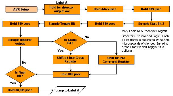
Software DesignThe AVR program featured here uses a special variant of the Phillips RC5 protocol that I adapted for personal uses. The basics of RC5 and the differences between this and RC5, will be discussed in this section. RC5 The Protocol When an RC5 remote operates, it sends the IR data with a 36kHz carrier frequency at a bitrate of 562 bits per second. This digital data consists of a single 14-bit frame. One the bit level, the RC5 remote control protocol uses biphase-L or "manchester" encoding. Here, to send a bit you first set the output high or low, then toggle that output. The figure on the right illistrates this a little better. As you can see, a single "0" bit consists of a high->low transition, while a "1" consists of a low->high behavior. Since each bit contains a level transition directly in the middle of each bit, you can essentially treat the transition edge as a clock signal. In this situation, we say the bits are self-clocking. Bit TimingEach full bit is 1.778ms wide. That's 889us for the leading half, and 889us for the trailing half. If we take modulation into account, the "on" period consists of a 36kHz square wave of 50% duty cycle (this 36kHz is also the carrier frequency). To minimise the number of hardware components, we will generate this squarewave will our software. To do this, we calculate: Tcarrier = 1/F = 1/36x10^3 ~= 27us 889us / Tcarrier = (889x10^-6)*(36x10^3) = 32 ...This tells us that the program needs to generate 32 square pulses that are 27us wide to represent the "on" period of an RC5 bit. Now that we can represent bits, we can link different bits together to create the 14-bit frame. The Data Frame FormatThe first two bits are called "AGC" or "AGCC" bits; that's "Automatic Gain Calibration" or "Automatic Gain Control Calibration. Their purpose is to let the detection module sample the signal's strength and find the optimum level of amplification. It can also let the software estimate the data rate. Both have a value of "0" (high->low transition). Next is the toggle bit. If you hold down a key on your TV remote, the frames will be repeated in rapid succession. However if you tap the key rapid-fire style, the frame will be repeated and the toggle bit will change on every keypress. This lets the TV distingsh between a key that is held down constantly, and a key that is tapped. The next five incoming bits are group bits. They declare whether the frame is meant to control a TV, VCR, DVD, or other equipment. Since n bits can represent 2^n numbers, this 5 bits allow 32 different groups. The final six bits are the command/data bits. Example commands are power on/off, volume up/down, channel select, play, stop, rewind, and so on. The six command bits allow 64 commands. The total frame time is 14*1.728ms = 24.192ms. After the final bit, the transmitter normally rests another 24.192ms before starting the next frame. To summarize:
An Example Here is an example RC5 frame. One you can see, the AGC bits are set to their standard "1" value for calibration. Note that the first bit is always mid-way complete before the receiver knows a transmission is active (a very odd feature). Recall that I mentioned that the mid-way level transitions my be treated as the clock, however not all transitions are actual clocks. Continuing, we read the group code MSB first to see that the target group is number 0x14 (group 20 in decimal); and the command is number 0x35 (53). Variations on RC5As mentioned before, I normally use something a little different from standard RC5 for communication purposes. The main differences are:
The other adjustments give the frames two direct advantages. First, the eight command bits work better for transferring normal 8-bit data. And for data and robotics applications, it seems much more practical to transmit in powers of 2. Second, the even parity bit makes it impossible to produce a frame consisting of all 1's. Thusly, this receiver can treat any all-ones frames as garbage. |
| Data |
Operational ReviewAfter processor noise issues are resolved, this simple circuit can perform suprisingly well. In indoor daytime conditions, the data range can extend about 2 meters beyond the nominal 10 meter range specified by the datasheet. The transmitter/receiver pair also function outdoors but this range was greatly diminished. Carrier and Bit Rate ReviewThe bitrate in the receiver were handled by a hardware timer interrupt, while the transmitter was handled with straight interrupt-free code. In my opinion, the interrupt-based approach was the best choice--since it allowed quicker debugging, more accurate timing, and was in general easier to understand. It also frees up a great deal of processor time to allow for other tasks, should the AVR need to carry out other functions. The timer-compare-match interrupt with Timer1 was especially helpful, and allowed me to keep the receiver timing error under 1.50us at all times. The AVR 2313 has only one timer with the compare-match feature, but luckily, the new and improved Tiny2313 has two. Error ReportsNo errors were detected when the transmitter and receiver were within their advertised range limits. This was tested with the Basic IR Transmitter project. When place outside the range of approximately 12 meters, the reciever's IR module would latch its output to 5 Volts during some bit streams, which likely would have triggered parity error detection. SummaryIn summary, both the RC5 receiver and transmitter projects worked perfectly indoors. If I were to make any improvements, I would add a parity check in the receiver code. Framing error detection (by extracting the clock from the manchester bits) could also be addded to filter out non-RC5 coded signals. |
| Reference |
|
RC5 Information Sources:
1. SB Projects. San Bergmans, Oisterwijk http://www.xs4all.nl/~sbp/knowledge/ir/rc5.htm 2. Davshomepage. De Vleeschauwer David http://users.pandora.be/davshomepage/rc5.htm3. Koninklijke Philips Electronics N.V. http://www.remotecontrol.philips.com/index.cfm?id=105. 2004-2005 |