![]()
![]()
![]()
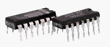
Integrated Circuits and Logic Gates
Electrical(switches) and electronic(diodes & transistors) circuitry can represent logic gates.
Integrated circuits (ICs) provide a more compact package of these gates.
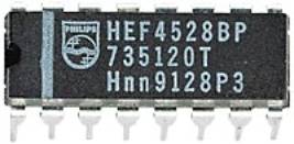
Using a protoboard or breadboard the gates TRUTH TABLES can be observed. Some combination circuits can be demonstrated.
|
|
QUAD 2 input AND There are four gates each with 2 inputs. Power (eg 9V) is connected between pins VDD and VSS |
|
|
|
|
|
QUAD 2 input OR Connecting 9V or 0V to the input pins, 1,2,5,6,8,9,12 & 13 will produce 9V or 0V at the outputs 3,4,10 & 11. |
|
|
|
|
|
QUAD 2 input NAND We need to use a multimeter or logic probe to measure the voltage or, we can use a resistor & LED to see if a voltage is produced. |
|
|
|
|
|
QUAD 2 input NOR If the LED lights it is at logic 1 and if it remains dark it is at logic 0. |


You can see how these are wired onto a protoboard here
or simulate the operation of the gates with a program here
![]()
![]()
![]()