xxxxxxxxxxxxxxxxxxx xxx xxx |
Before
we get started, i'll just go over a few of the basics, in case you're
a complete novice.3D Studio max is a very comprehensive program and
in making this little guy we will only scratch the surface of its capabilities.
To begin with we have to create a box so look around on a tab panel
to the right of the screen until you find a little arrow with a star
at its point. This is the create tab, click on it to see all the options.
It should default to "Standard Primitives" which is cool because
we want to create a box. Click on the "Box" button and it
will turn green. Take your crosshair cursor into the "Top"
viewport and draw out a roughly square object. In this view you wont
be able to see the height but cast your eyes to the "Perspective"
port and you should be able to see the height. Have a few goes at it
before you settle on one box or another. Your starting point will be
a box that is roughly 1 x1 x 3 length, width, height respectively.
Okay,
now we have our box, the fun begins. Go to the tab panel again and find
the tab with the sort of blue rainbow motif.
this is the "Modify" panel. I prefer to do my settings here
because all of the rest of the modelling here is done with this panel
open. The parameters of your box will be dispayed ONLY if you still
have it selected. To make this phase easier, go to the "Perspective"
viewport and select "Wireframe" by right clicking on the word
"Perspective" . Your box should now just be represented by
lines. In the modify panel you will see the readouts for lenght, width,
height and selectors for segmentation. Set the segments 4,3,4 length,
width, height. Next, we want to make our box into an editable mesh,
so we can either collapse it by clicking on the little symbol that looks
like a stack of paper or we can apply an "edit mesh" modifier
to it. i normally just collapse because I know that i won't need to
go back in the "stack" to modify the box. However, if you
want to work ina purely proceedural way, you may want to just slap the
modifier on it.
|
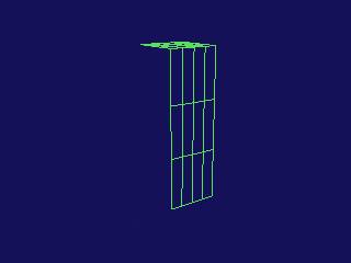 |
Lets get
down to business. First of all we want to delete all of the polygons
on the side of the mesh that we will be mirroring to. We are only going
to model half the head to begin with. So go to the modify panel and
find the "Sub Object" button. When active, this mode allows
you to manipulate any part of the box in any way needed. First click
the button with a little square symbol (not the triangle) this is "polygon"
mode. Rotate your box in the viewport until you are looking at the left
hand side. Click in one of the squares and it will turn red, it is selected,
hold down your "alt" key and select the rest on this side.
With all of the squares showing red hit the "delete" key on
your keyboard and answer "yes" to any dialogs that appear.
Yor box should now lok like the one to your left.
|
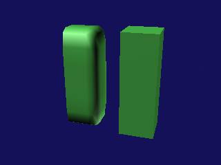 |
Next, we make
a REFERENCE of the box by holding down "shift" on the keyboard
and dragging out the copy in the "X" direction. If you cant drag,
you probably have "select" mode rather than "move" mode
selected on your top panel (select is default ). Now, click on your reference
box and go to "More" at the top of the modify panel. Clicking
on 'more' gives you a list of all the currently installed modifiers. Find
"Mesh Smooth" and click on it. It will apply itself to the box
automatically and will give you a result like the pic on the left. |
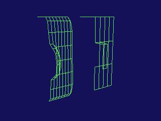 |
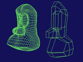
Now, go back
to your original box and hit "Sub Object". Hit the "Polygon"
mode up again and select the leftmost middle poly. Go down the panel and
find the "Bevel" tool hit the button and it turns green. Move
your cursor back to the selected poly, click and drag over it. Depending
on the normals, the poly will either go in or out. Get it to extrude out
and then when its far enough out for you let the mouse key up. This is the
bevelling part of the operation. The selected polys will shrink, then, if
you go too far, they'll cross over and make a big mess. just tickle them
to a slightly smaller square shape and you'll have some thing similar to
the illustration. After this operation it is essential to delete
the left facing poly of the newly extruded bit. If you dont the mesh
smooth will screw up. When we come to finish this model we will have two
identical halves that will have to be welded together. If there are any
internal polys or polys facing eachother at the joint, the whole thing will
go WRONG and you'llbe really ticked off. |
|
It
is really handy to use "snaps" when cutting. look for a little
button at the bottom of the page with a magnet symbol on it. There are
three options 2D, 2.5D and 3D. We want 3D and then right click on the
button. Set the options to "Edge" and un-tick all the rest,
then close the window with the "X" button
|
We can begin
really moving the polys and start forming the shape now. The beauty of this
is that the result is in front of your eyes as you work. Anything that goes
wrong is just an "undo" away from being re-done the right way.
Now that you have mastered "Bevel" you can use "Extrude "
to make the eye socket. Use it the same as Bevel but in this case there
is only one operation per click and drag. I have used "Cut" here
to make the socket a better shape. to use "Cut",
find it in the panel then click on the button. This can be a tricky manouver,
so keep that undo button handy. With the cursor over the vertical line you
want to cut, click once and then move to the line you want to cut to and
click again. There should have been a dotted line following the cursor and
after the second click, aline should appear between the two points, indicating
a successful cut. Practise this until you get it down, we'll be doing more
cuts. |
 |
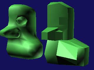
I'm
well into the modelling here and i've done a wild and crazy thing!! I have
made another reference of my reference with the "Mirror" command
on the top tool bar. Look for two triangles facing eachother with a line
vertically betwwen them on the button. The new reference is a mirror of
the previous one and has now furnished me with an almost complete reference
model. I have also bumped up the iterations to 2 on the mesh smooth to make
the refernce look a little better. I have also moved a lot of the polys
around by their intersection points known as vertices. To manipulate at
vertex mode hit the button with the dots on in your Sub Object panel |
|
|