NETWORK TOPOLOGY
|
NETWORK ARCHITECTURE
|
CLASSIFICATION OF NETWORK
|
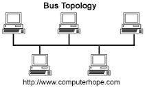
BUS TOPOLOGY
|
A bus topology consists of a main run of cable with a terminator at
each end. All nodes like workstations, printers, laptops, servers etc.,
are connected to the linear cable. The terminator is used to absorb the
signal when the signal reaches the end, preventing signal bounce. When
using bus topology, when a computer sends out a signal, the signal
travels the cable length in both directions from the sending computer.
When the signal reaches the end of the cable length, it bounces back
and returns in the direction it came from. This is known as signal
bounce. Signal bounce will create problem in the network, because if
another signal is sent on the cable length at the same time, the two
signals will collide.
|
|
RING TOPOLOGY
|
A ring topology is a network configuration in which device connections create a circular data path.
Each networked device is connected to two others, like points on a
circle. Together, devices in a ring topology are referred to as a ring network. In a ring network, packets of
data travel from one device to the next until they reach their
destination. Most ring topologies allow packets to travel only in one
direction, called a unidirectional ring network. Others permit data to move in either direction, called bidirectional. |
|
STAR TOPOLOGY
|
Alternatively referred to as a star network, star topology is one of the most common network setups. In this configuration, every node connects to a central network device, like a hub, switch, or computer. The central network device acts as a server and the peripheral devices act as clients. |
|