Splines on their own aren't much at all: just a mathematical description of a curve in space, an idea of the path traced out by a point moving from one location to another. Splines become really useful when we can use them to control aspects of our POV-Ray scene. Perhaps the most obvious use is creating objects based on the shape of a spline path, so let's do just that:
#declare ObjectSpline = create_spline (
array[4] {<-2, 0, 0>, <0, 15, 5>, <2, 0, 0>, <0, 15, 5>},
create_hermite_spline)
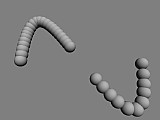
create_spline_object (ObjectSpline, default_options)
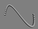
Using the default options what we get is a string of white spheres spaced out along the spline. Granted, it's not a very exciting object , but it does show us an important aspect of cubic splines. Looking at the spheres we can see that the spacing between each sphere is not the same - some spheres actually overlap while others are completely separated. The changes in the spacing indicate the acceleration and deceleration that takes place as the spline curve is traced out.
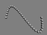
Sometimes these changes in speed are just what we want, for example when we are animating objects using splines. At other times we want the spacing along the spline to be constant. To do this we must introduce a new option when we actually create the spline:
#declare ObjectSpline = create_spline (
   array[4] {<-2, 0, 0>, <0, 15, 5>, <2, 0, 0>, <0, 15, 5>},
   create_hermite_spline + spline_sampling (on))

create_spline_object (ObjectSpline, spline_steps (30))
Using the spline_sampling option actually samples positions along the spline curve, which are stored and then used to more accurately calculate the length and spacing of the spline. To improve the accuracy of the calculations we can increase the sampling option, eg. spline_sampling (2) would use twice as many samples as above. Adding more samples does slow down parsing and increase memory usage, so it's best to use the lowest value that gives acceptable results. Another option that can help here is spline caching, especially when we want to create a complicated spline with many samples - see the Spline Macro File documentation for more information.
To give you an idea of the sorts of objects you can create using splines, here are some examples (all using the previously declared ObjectSpline). Each shows different options that can be used when creating spline objects.
The pipe spline uses spheres, cylinder and cones to create a smooth pipe along the spline curve. Here we also use the spline radius option and the spline radius function to adjust the radius of the pipe along the spline.
#macro spline_radius_function () cos(sClock*4*pi) #end
union { pipe_spline (ObjectSpline, spline_radius (0.25))
   pigment {bozo color_map {[0 rgb <1, 0, 0>] [1 rgb <1, 1, 0>]} scale 0.5}
   normal {crackle scale 0.1}
   finish {specular 0.3}
   }
We can use the link spline to create all manner of objects by linking smaller objects together along the length of the spline curve. Here we also use the spline step size option to set how long each link should be, and the spline step twist option to set the number of degrees each link is twisted around the spline.
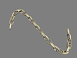
#declare link_object = torus {0.7, 0.1 scale <1, 1.5, 0.6>
   pigment {rgb <1, 0.9, 0.6>}
   finish {reflection 0.4 specular 0.5 metallic}
   }
link_spline (ObjectSpline, spline_step_size (0.3) + spline_step_twist (60))
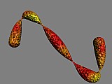
Blob splines are similar to pipe splines, but because we use blobs the results are often smoother. We can also use a vector for the spline radius option to flatten the blob in one direction.
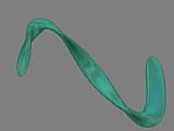
object { blob_spline (ObjectSpline, spline_radius (<0.4, 0.1>)
   + blob_stretch_factor (3)
   + spline_total_twist (1.5 * 360))
   pigment {rgbf <0.5, 0.9, 0.8, 0.8>}
   finish {irid {0.3 thickness 0.4}}
   }
As the name suggests, torus pipe splines work by placing torus objects along the spline curve. We can use this to create quick, smooth curves with a low spline steps value (sacrificing a little accuracy), or using extra options to make some very interesting objects.
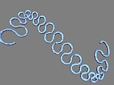
union { torus_pipe_spline (ObjectSpline, spline_steps (30)
   + spline_radius (0.05)
   + initial_torus_tangent (<-1, -1, -1>))
   pigment {rgb <0.5, 0.9, 1>}
   normal {wrinkles 1 scale <10, 1, 1>/20}
   finish {ambient <0.5, 0.2, 0.3> diffuse 0.8}
   }
The coil spline is similar to the torus pipe spline, but the torus segments are specially arranged to form a coil around the spline curve.
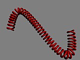
union {coil_spline (ObjectSpline, spline_steps (80)
   + spline_radius (0.2)
   + coil_radius (0.05))
   pigment {rgb <1, 0, 0>}
   finish {phong 0.6}
   }
We can see in the examples shown how the same spline curve has been used as the basis for many different objects. To make splines even more versatile we can transform the curve itself before we use the spline (to create objects or otherwise), using the following options (added to the other options):
spline_scale ([a number or vector])
spline_rotate ([vector])
spline_translate ([vector])
spline_portion ([start], [finish])
The first three options transform the spline in the same way as the scale, rotate, and translate keywords transform POV-Ray objects. We should note, however, that no matter which order we specify the options in, the spline transformations will always take place in the scale, rotate, translate order.
The final option lets us create objects along just a section of the spline curve, for example, adding spline_portion (0.5, 1) to any of the above examples would create the objects only along the second half of the spline curve. We can also reverse the direction of the spline object by making the start of the portion larger than the finish, and we can even use number outside the 0 to 1 range if we want to loop through the spline multiple times.
While the predefined spline objects we saw earlier allow us to create many, many different spline objects the Spline Macro File also lets us use the full power of POV-Ray's macro features to create completely custom spline objects. This way, we can dictate exactly what happens at each and every step along the spline, and how we want to step along the spline's length.
To create a custom spline object we must first define a spline object macro that creates the objects we want. Then we call the create_spline_object macro with the spline object options we want to use. In the spline object macro we can use any of the following values in the creation and manipulation of our objects:
spline_radius and/or spline_radius_function options)spline_step_twist and spline_total_twist options)After the first step we can also use the pStep, pProgress, pClock, pPos, pTangent, pAccel, pDist, pRad, and pTwist values to refer to the values of the previous step. To get a feel for how these values operate, let's try a simple custom spline object:
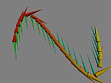
#macro spline_object ()
   cone {sPos, sRad, sPos + vnormalize(sTangent), 0
      pigment {rgb <1, 0, 0>+sProgress*(<0, 1, 0>)}}
   #if (   vzero(sAccel))
      cone {sPos, sRad/2, sPos + vnormalize(sAccel), 0
         pigment {rgb <0, 1, 0>+sProgress*<0, 0, 1>}}
   #end
   #debug concat("Step #", str(sStep, 0, 0), ": distance travelled = ", str(sDist, 0, -1), " units\n")
#end

create_spline_object (ObjectSpline, spline_steps (20) + spline_radius (0.1))
As we can see the red/yellow cones point in the direction of travel, whereas the green/cyan cones point in the direction of acceleration. Looking at POV-Ray's debug text stream we can also see how the distance travelled changes along the length of the spline. (Note: the vzero () function is a macro defined in the Spline Macro File, which we can use to check if a vector is of zero length).
Most of the variables we have access to when creating spline object macros only return information about the spline. Some of them, however, can also be changed to adjust how we step through the spline, namely sStep, sProgress, sDist, and sClock. Incrementing or decrementing any one of these in the spline object macro will move the spline position forward or backward for the next step by the amount we specify. For example, if we wanted to use half steps for the first portion of the spline, skip the middle section, and then step through the remainder by equal unit distances (regardless of how many steps have been specified), we could use something like this:
#macro spline_object ()
   sphere {sPos, sRad}
   #switch (sProgress)
   #range (0, 0.4) #declare sStep = sStep + 0.5; #break
   #range (0, 0.6) #declare sProgress = 0.6; #break
   #else        #declare sDist = sDist + 0.3; #end
#end

union {create_spline_object (ObjectSpline,
   spline_steps (25) + spline_radius (0.2))
   pigment {rgb 1}
   }
When creating spline object macros you can also use the torus_arc, pipe_spline_object, link_spline_object, coil_spline_object, and fit_to_spline_step macros in combination with actions like those shown above - see the Spline Macro File documentation for more information.