To render the example files in this tutorial with POV-Ray you will need to download and install the Spline Macro File. The ZIP package (11 Kb) includes Quick Reference documentation, and the macro file itself, spline.mcr, which should be copied to one of the directories in your list of POV-Ray library paths (e.g. C:\Program Files\POV-Ray for Windows 3.1\Include).
If you've used the lathe or prism object in POV-Ray you should have a pretty good understanding of how splines work. The Spline Macro File lets you extend this idea of a curved shape into POV-Ray's full 3D space, so you can design paths that twist and turn and loop back on themselves in whichever way you wish. Then, you can use these paths to animate objects or to create objects based on the shape of the spline path.
Specifically, the Spline Macro File lets you create cubic interpolating splines. "Cubic" simply means the maths of the spline uses cubed functions - all we need to know is that this lets us create smooth, flexible curves. "Interpolating" means that the curve passes through each of the points we tell it to, so we know exactly where the path will travel. The Spline Macro File actually lets you create these cubic interpolating splines in four different ways, and gives you extra options to better control the shape of the spline path.
To start, let's create a simple spline path and view the result:
camera {location <0, 0, -4> look_at <0, 0, 0>}
light_source {<100, 200, -300> rgb 1}
background {rgb 0.5}

#include "spline.mcr"

#declare MySpline = create_spline (
   array[4] {x, y, -x, -y},
   create_default_spline)

preview_spline (MySpline, default_options)
After defining our basic scene settings (camera, lights, and background) the first thing we do is include the Spline Macro File. This gives us access to the functions of the macro file, just like including textures.inc gives us access to POV-Ray's predefined textures. Note that we only need to include the Spline Macro File once at the beginning of our scene, even if we create many different spline paths.
To actually define our spline path we must declare it using the create_spline () macro function. This is just like declaring any other POV-Ray object or value, and the same rules apply to naming our spline identifier. Also, because create_spline is a macro function we use curved brackets () rather than the usual braces {}.
The create_spline function requires us to first specify a list of points we wish to interpolate. We do this using POV-Ray's array feature, specifying the number of points as shown. This list of points is followed by a list of options we wish to use when creating our spline path; to start, we simply want the default spline so this is the option we specify.
Finally, having created our spline path we can quickly preview the shape of our path using the preview_spline () function. Again we use curved brackets, inside of which we specify the identifier of the curve we want to view, followed by the options we want to use (the default options, in this case).
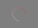
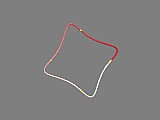
When we render this scene we will see that the spline path is a smooth curve that passes through each of the four points we specified (shown in yellow). Notice also that the colour of the previewed spline changes from red at the first point to white at the last: this lets us know which direction the spline is travelling in.
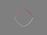
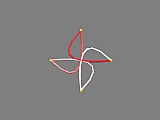
Now that we've created a spline it's not too hard to see how we could change its shape by adding extra points that we want the spline to pass through. But looking at our first spline we can also see that there are many possible curves we could have drawn through our points, not just the one created before. So, in addition to altering the spline points we can also change the shape of our spline using a number of options. The simplest is the spline_loop option that makes the spline loop back to its beginning. To use this option, we add it to our create_spline () option list like this:
#declare MySpline = create_spline (
   array[4] {x, y, -x, -y},
   create_default_spline + spline_loop (yes)
   )
It's important to note that we use an actual addition (+) between the options, rather than commas or plain spaces. Also, because we are using macro functions we surround our option value with curved brackets (). Rendering the above spline shows that the curve does indeed loop back on itself.
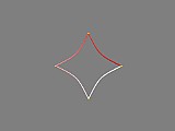
Another option we can use is the spline tension value, that changes how tight the spline curve fits through the points. If we increase this value above the default of zero, we can see how the curve tightens:
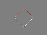
create_default_spline + spline_loop (yes) + spline_tension (0.5)
and if we reduce it less than zero, we can see how the spline loosens:
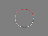
create_default_spline + spline_loop (yes) + spline_tension (-1)
Good values generally range from -1 to 1 (which actually tightens the spline so much the curves become straight lines between each point). We can also use values outside this range to create some pretty strange spline curves...try it and see
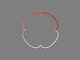
The next option we can try is the spline bias value: like the spline tension this is normally zero, which means that the spline is curved equally on either side of each point in the spline. If we increase this value we can see how it makes the spline path more curved on one side of each point than the other:
spline_loop (yes) + spline_tension (-1) + spline_bias (1)
Using a value of -1 would reverse the effect. Again, values outside the -1 to 1 range can be used for more eccentric curves.
The third option can we use to adjust the spline shape is the spline continuity value. Looking at the previous splines we can see how the path always travels smoothly through each point - there are no sharp corners. The continuity value lets us change this, by using values other than the default of zero, eg:
spline_loop (yes) + spline_continuity (2)
or:
spline_loop (yes) + spline_continuity (-2)
Earlier we saw how increasing the spline tension to 1 allowed us to create a straight line spline path. We can also achieve this by leaving the tension at 0 and increasing the continuity to 1. The results of either look pretty much the same, but they are actually quite different and in general you should use this second method (changing the continuity) to create linear splines (for reasons we shall see later...).
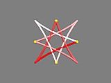
By now we can see how there are an infinite number of possible curves that can pass through a given set of points, and using the tension, continuity, and bias values in various combinations allows us to create many of them. One trick we can use when designing splines is the shortcut spline_TCB option: this allows us to specify all three values in one set of brackets, eg:
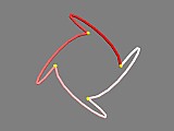
spline_loop (yes) + spline_TCB (2, 2, 2)
or:
spline_loop (yes) + spline_TCB (3, -1, -1)
or:
spline_loop (yes) + spline_TCB (4, -3, 0)
For the technically minded, using the tension, continuity, and bias values creates what is known as a TCB spline, or Kochanek-Bartels spline (after those who pioneered it) - this type of spline is quite common in professional 3D modelling software. Using just the tension value to adjust the spline creates a cardinal spline, and leaving the TCB options at their defaults of zero creates a Catmull-Rom spline (again quite commonly used in other software). The last two are subsets of the first, and all the different types are indeed cubic interpolating splines.
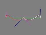
There is another common cubic spline you are probably aware of: the Bezier spline. This type of spline is used in many 2D design software packages as well as POV-Ray bicubic patch and other spline objects, and is characterised by the use of control handles at each point. These handles set the curvature of the spline, and can be adjusted for sharp corners, tight or loose curves, etc. To create bezier splines with the Spline Macro File, you specify a list of points where every third point is actually interpolated (ie. joined). The two points between each joined point set the ends of the control handles used to shape the spline path, eg:
#declare MyBezierSpline = create_spline (
   array [7] {<-2, 0, 0>, <-2, 1, 0>, <-1, -1, 0>, <0, 0, 0>, <1, -1, 0>, <2, 1, 0>, <2, 0, 0>}
create_bezier_spline)

preview_spline (MyBezierSpline, spline_accuracy (2) + show_spline_hull (yes) + show_spline_tangents (yes))
You will notice also that we've used some new options in the preview_spline () function, improving the accuracy of the spline path, and making visible the hull (the connections between the spline points) and the tangents (the direction the spline path is travelling before and after it reaches each control point, ie. the Bezier curve handles). Other spline preview options are listed in the Spline Macro File reference.
Bezier splines have the advantage over TCB splines of allowing you to set the curvature of the spline directly for each section, so you can create some sharp corners and some smooth, and generally have more control over the spline's shape.
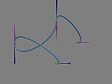
Another way you can control the curvature of the spline at each point is to create a hermite spline: this is expressed as a list of pairs of points and tangents (ie. the velocity the spline is travelling at). This allows you to create smooth curves but have direct control over the curvature at each point, eg:
#declare MyHermiteSpline = create_spline (
   array [8] {x, x*2, y, -y*3, -x*2, y*3, -y, -x*2},
   create_hermite_spline)

preview_spline (MyHermiteSpline, spline_radius (0.03) + spline_accuracy (2)
   + show_spline_tangents (yes)
   + spline_preview_pigment (pigment {rgb <0.5, 0.8, 1>})
   + spline_preview_finish (finish {phong 0.5}))
Here we join x to y to -x to -y, but the direction at each point is set by the tangent specified after it. Changing the length of the tangent changes how much the path is curved. We can also adjust the tension and bias values for both Bezier and hermite splines, to adjust all our tangents according to the values we specify.
There is a final spline type you can create with the Spline Macro File, using the create_cubic_spline option. This allows you to create a default TCB spline as we first encountered, but the spline only connects the points from the second to the second last. The very first and last points are used to set the curvature of the spline at the beginning and end, just as with POV-Ray's cubic spline used in the lathe and prism objects.