 |
|
richardandtracy's Plywood Dingy 'Rime'.
This article is about how to make my ultra cheap 8ft dingy design which, rather pretentiously, I've called 'Rime'. The dingy is a 2 sheet plywood design that can be rowed or sailed, but will need an extra bracket for an outboard. The design was inspired Phil Bolger's 'Brick', but as I've never seen anything other than a small, grainy, photo of a 'Brick', the likeness is only skin deep. 'Rime' looks as below with its sail:-
The picture below is of 'Rime' the day it was launched in August 2006 as a rowing dingy. I have to complete the sailing gear, but that'll come eventually. The bow is on the right of the photo, if you need to be told!
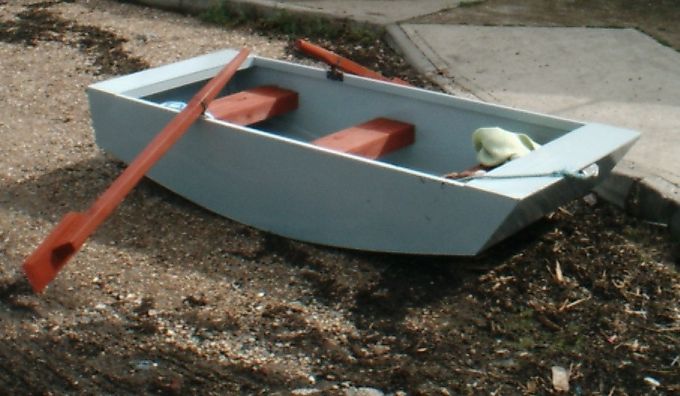
When I designed 'Rime' I came to the conclusion that I could make it for £45, however since then most of the prices have gone up by much more than inflation, and I think £60 is nearer the mark for everything including sails and oars if you have to buy everything. The hull actually cost me £26.43p in August 2006 because I was able to use bits from pallets for the timber, and I had been given the paint & stain. This compares quite favourably against approximately £1000 for a 'cheap' commercially produced sailing dingy (£1000 is not my idea of 'cheap' I may add!).
The article is split into several sections (all on this one web page), as below:-
Description
Drawing
Parts List
The Hull
The Thwarts
The Rudder
The Dagger Board
The Mast
The Sail
The Oars
Miscellaneous bits
Final Assembly & Finishing
In Use
Description
Rime has been designed as a stable workhorse dingy/tender that is as close to being a disposable boat as possible. The dingy should take two adults and two children in sheltered waters, or two adults in less sheltered waters. The freeboard is as great as I can manage while still only using two sheets of ply. The design is such that it can be stern launched from any height by its painter without shipping water (provided the hull weighs less than 50 kg [110 lb] - and heaven help you if you've made it so it weighs more than that!). 'Rime' is distinctive, but it isn't pretty, features which should deter thieves.
The woodwork of the hull should take no more than a weekend to shape and glue. The sides are vertical and parallel, while the bottom is curved to match the sides (this increases stability while reducing work compared to a more traditional shape). The hull construction method is a glue and staple method (using 15mm pins from a staple gun). Then, when the glue has set, the seams are taped with glass cloth.
The rudder is designed to flip up in shallow water. The daggerboard is a single piece of plywood designed to fit in a slot on the outside of the hull - a feature that eases manufacture.
The mast is a simple slot in affair offset to one side of the dingy to give the maximum space. The yard and boom are both made from two strips of timber screwed together, clamping the tarpaulin sail between them.
Designs for all the fittings used on the dingy are given. As designed, the metal fittings are manufactured from mild steel, and are consequently massively oversized to allow for a significant corrosion allowance.
Where possible I have used scrap materials available to me. Much of the timber is sized to be taken from old pallets, and the steel is designed to come from a scrap steel skip.
Return to Index
Drawing
A full drawing is available for download here. If you download the drawing you'll be able to plot a 1:1 scale profile of the boat (assuming access to a plotter that can produce 8ft [2440 mm] long drawings). This will make the initial layout much easier for you and I do recommend it. The other advantage of the drawing is that all the piece parts are available for 1:1 plotting too.
Download the DXF file. [Sorry, the drawings are not ready yet]
Download the AutoCAD R14 drawing file. [Sorry, the drawings are not ready yet]
Return to Index
Parts List
In my normal way, I have made this into a fully itemised engineering drawing with a Parts List, as below:-
Return to Index
The Hull
The hull is the biggest, but not the most difficult part of the dingy. For the hull you will need two sheets of 6mm plywood 8ft x 4ft. They need not be marine ply, but do make sure they're WBP (water and boil proof) - this uses the same glue as marine ply. Then mark out the cutting lines as below:-
Dimensions for the rectangular parts can come off the Parts List, however unless you've plotted the side of the dingy 1:1 you'll need co-ordinates for the side. These are tabulated below, starting at the stern, with X forward and Y being the distance from the gunwale (edge of the sheet). The curve of the sole is from co-ordinates 2 to 11. The lowest point is co-ordinate 6.
| Co-Ord No. |
X |
Y |
| 1 |
0 |
0 |
| 2 |
50 |
283 |
| 3 |
300 |
339 |
| 4 |
600 |
396 |
| 5 |
900 |
432 |
| 6 |
1106 |
441 |
| 7 |
1200 |
438 |
| 8 |
1500 |
412 |
| 9 |
1800 |
360 |
| 10 |
2100 |
292 |
| 11 |
2237 |
256 |
| 12 |
2417 |
0 |
Now you need to make up some panels. Start with the..
Stern.
Make one off item 31 (Stern Stiffener, Top) from 953mm of 45 x 19mm PAR (planed all round) softwood, and plane down to the end section below:-
Make 2 off item 32 (Stern Stiffener, Side), which is 45 x 19 PAR, 208mm long.
Make one off item 33 (Stern Stiffener, Base) from 953mm of 45 x 19 PAR softwood, and plane down to the end section below:-
Now, attach Item 33 to the base of Item 22, so that the 36mm dimension is against the ply, and the 44mm dimension creates an 8mm overhang over the edge of the ply. The timber is to be positioned centrally on the ply, so that there is 6mm of ply at either end. Attach Item 33 with waterproof wood glue and 15mm brads from a stapler (the brads will hold it while the glue sets). Then position Items 32 and 31 relative to these pieces. On Item 31, the 44mm dimension is to be against the ply, as below:-
Now plane the edges of the ply to match the bevels on items 31 & 33.
Bow
The bow is made in the same way as the stern. Make one off Item 35 (Bow Stiffener, Top) from 953mm of 45 x 19 PAR planed down to the section below:-
Make 2 off item 36 (Bow Stiffener, Side), which is 45 x 19 PAR, 249mm long.
Make one off item 37 (Bow Stiffener, Base) from 953mm of 45 x 19 PAR softwood, and plane down to the end section below:-
Now, attach Item 37 to the base of Item 24, so that the 22mm dimension is against the ply, and the 44mm dimension creates a 22mm overhang over the edge of the ply. The timber is to be positioned centrally on the ply, so that there is 6mm of ply at either end. Attach Item 37 with waterproof wood glue and 15mm brads from a stapler (the brads will hold it while the glue sets). Then position Items 36 and 35 relative to these pieces. On Item 35, the 44mm dimension is to be against the ply, as below:-
Now plane the edges of the ply to match the bevels on items 35 & 37.
Sides
The first thing to sort out is the gunwale. Make two off Item 26 (Gunwale) from 2375mm of 45 x 19mm PAR. Mitre the stern end at +80 degrees, the bow at -55 degrees, as shown below:-
Now make two half check joints (cut a slot 19mm wide x 22mm deep in the top (long) surface of the gunwale. One slot starts 185mm from the stern end, and the other 180mm from the bow. These half check joints are as complicated as the carpentry gets, and are intended to make the bow and stern top panels as strong as possible.
Here come the most difficult bits in the hull, the sole boards. Two off each of the three sole boards are needed (Items 27 to 29). These are to be cut as below:-
Now you need to mark out some position lines on the side panels to be able to accurately position the sole boards (may be most convenient to do before cutting the ply). These are at:-
Stern: 247mm along stern angle from gunwale.
Joint 1: X = 840mm, Y = 397mm
Joint 2: X = 1444mm, Y = 396mm
Bow: 257 along bow angle from gunwale.
Now position items 27 to 29 along these lines (aft to forwards). The timber will overhang the sole. Mark this overhang, and cut it back to match the sole line. Once complete attach the gunwale and sole boards to the side by pinning & glueing. Use the Stern Panel to ensure that the gunwale is the correct distance from the aft edge of the side panel (approx 19.25mm). Remember to ensure that the timber is on the inside of the dingy! The completed side will be as below:-
If you wished to you could attach the thwart and mast supports to the side panel now.
Bow & Stern Top Panels
You need two off Item 38 (Support, Top), made from 953mm of 45 x 19mm PAR, with half check joints at each end as below:-
Now pin and glue these to the centre of the long edge of items 23 and 25.
Assembly
Now pin and glue all the panels you have together, upside down on a flat surface, as below:-
Now leave the glue to dry overnight.
When the glue is set, glue, pin and possibly screw the sole panel to the curved edges of the hull presented to you. Plane off the unfair edges of the sole. That completes the hull bonded assembly for now. We will come back later to finish it off.
Now for a bit of pure speculation.. If you were to make the sole (Item 21) from 9mm (or there abouts) thick clear PVC sheet you'd have a 'Glass Bottomed Boat'. The PVC sole could be attached with screws and a flexible mastic adhesive. Not as daft as it sounds - particularly if you live in an area with clear water.
Return to Index
The Thwarts
Positioning of the thwarts is a very personal matter, which is why I've not included it in the main hull assembly. I suggest that you consider the positions I've given, and modify them if you wish.
Each thwart is made from 12mm birch ply (chosen because I have some lying around after completing the interior of my camper) supported by two thwart supports. The 12mm ply could be replaced with 6mm and an extra seat support or something equally substantial. The sizes may be obtained from the Parts List. You need three seats (item 41) and six seat supports (item 42). The seat supports are pinned/ screwed and glued to the long edges of the seats to form the thwart assembly (item 4).
Now cut six off thwart supports, 44 x 19mm PAR, 192mm long. These are to be screwed and glued horizontally to the hull sides with the aft top corner having the following co-ordinates (datum as before):-
| Thwart |
X |
Y |
| Aft |
292 |
162 |
| Mid |
1052 |
196 |
| Fwd |
1880 |
162 |
Screw & glue the thwart assemblies to the thwart supports.
Return to Index
The Rudder
The Rudder Assembly (Item 5) looks as below:-
There are four assemblies that make up the rudder. These are detailed individually below:-
Rudder Box Assembly
Start the rudder box assembly with the tiller. This should start life as a 40mm (or more) square timber that's 900mm long. Then cut the three parts of the rudder box (Items 47 to 49). Glue and screw Item 47 firmly to the tiller with at least 3 screws. After that, snape off the corner of Items 49, drill the 12mm dia rudder pivot hole, and assemble the rudder box as below:-
Now, if you wish, you can plane down the sides of the tiller handle to make it more comfortable to hold.
Upper Pintle Fabrication
The upper pintle fabrication could be a bought item - but I prefer to make my own. It's designed to be made from two pieces of scrap steel. A 20mm dia bar turned up on a metal lathe and some 25 x 2mm strip. The assembly looks as below when welded together:-
And the view from below (different scale just to confuse you!).
Lower Pintle Fabrication
The lower pintle fabrication is made in the same way as the upper fabrication
The view from below is identical to the upper pintle, so just to repeat it:-
Cam Cleat
The cam cleat is another steel fabrication. The first is the cam fabrication (Item 18) as drawn below:-
And now the Cam Base (item 19) fabrication made from more 2mm x 25mm strip. The three holes are intended as adjustment depending on how much the rope compresses when you use it.
Bolt the two bits together using an M6 screw or bolt. If you have the facilities, make a shouldered bolt with an 11mm long shoulder.
Now it's back to making the rudder. The lifting part of the rudder (Item 74) is made from 12mm birch ply and is drawn as below:-
The 8mm and 6mm holes are for shock cord and rope respectively. The shock cord pulls the rudder down, while the rope is used to raise the rudder. The underwater profile of the rudder is chamfered back 4mm x 25mm on both sides to give a better hydrodynamic profile.
Now varnish all the woodwork and paint the steel (if you want). The pintle assemblies should be attached to the rudder box with wood screws with the lower strap along the bottom of the rudder box, and the upper one at a distance of 223mm from the lower one.
You will need an M12 pivot bolt (50mm long) and a lock nut. Failing that, make up a shouldered bolt with a 40mm long shoulder. Attach the cam cleat to the top of the tiller with 4 wood screws (no, I haven't shown the screw holes in the drawing..) and feed the rope from the 8mm hole in the rudder through it. The end of the shock cord from the 6mm hole cam be stapled to the tiller with fencing staples.
That's the rudder done.
Return to Index
The Dagger Board
The daggerboard and its brackets are pretty simple to make. The daggerboard is just a strip of ply with a stop at the top which slots into two metal brackets on the starboard side of the boat. The Daggerboard and stop (Items 72 & 73) are drawn below:-
The stop is screwed to the dagger board with three screws.
Two metal dagger board brackets (Items 43) are made from 25 x 2mm steel strip to the form below:-
These straps could be made from timber if you wished. It's up to you.
Return to Index
The Mast
The mast consists of the mast (wow!), the brackets to attach it to the hull, the hull stiffener timber and the various cleats and brackets on the mast.
Let's start with the mast. The mast is made from a 2200mm length of 45mm x 45mm PAR softwood shaped as in the drawing below:-
The circular section is just for preference. You could plane it off octagonal if you wished. The 9mm chamfer on the case is to get it to lie evenly on the sole of the boat.
Now for more metalwork. Two off of the Mast Bracket (Item 44) are to be made from 25 x 2mm steel strip, as below:-
And one Mast Mid Bracket (Item 70):-
Item 70 is optional, but I think it's a good idea, and if you do include it you need one off Item 34 (Mast Support Timber) to be made from 279mm of 44 x 19mm PAR. A 77 degree mitre must be cut in one end.
Item 34 is then to be attached to the starboard side of the hull 45mm aft of the forward thwart by pinning ind glueing. The timber is to be vertical and butting against the gunwale and the forward sole support.
More metalwork.. This time it's the mast cleats (Item 61). You need four of them. They're welded up from 6mm dia steel rod onto yet more 25mm x 2mm steel strip (yes, I did find a lot in a skip!). The drawing is as below:-
I didn't show the screw holes necessary in the strip for attachment to the mast - I leave those up to you.
Now the pulley for the top of the mast (Item 63). I suggest you make a pulley block to the design shown in my Pulley Design page for a 6mm rope (D = 6mm). Either make it so that the pulley is fixed to the top of the mast or it hangs from a bracket like the one shown below (Item 60, welded up from 6mm steel bar and 2mm x 25mm strip):-
Screw the cleats and brackets to the mast, and they go together in the dingy as shown below (looking from the stern quarter):-
That's the mast finished.
Return to Index
The Sail
The sail area is 38.9 square feet (3.59 square metres), supported by a yard and boom made from 44 mm x 19mm PAR timber screwed together through the sail. The two yard timbers (item 68) are as below:-
The two boom timbers (item 67) are as below:-
Make 3 off Spar Cleats (Item 64) from 25mm x 2mm steel strip and 6mm dia bar as below:-
Make a Forward Boom Cleat (Item 65) from 25mm x 2mm steel strip and 6mm dia bar as below:-
Sail
The sail is made from either a thin tarpaulin or Tyvek building paper (you know, that infuriating stuff sometimes used to make envelopes you can't rip open). The shape is as below:-
Assembly of the sail
The yard and boom should be suitably weather protected (if you wish) with varnish. Then attach waterproof carpet tape (Item 17) to the topside of one of the yards, and stick edge A of the sail to the tape. Attach more tape to the top of the sail above the yard, and stick down the second half of the yard. Screw through the top yard to the bottom yard with Item 66 (35mm [1.5"] long wood screws) every 150mm or thereabouts. Repeat the procedure with the Boom on Edge B. On the unattached edge you can stick on a doubler of sail material to strengthen the edge - it's up to you.
Now to attach a spar cleat (Item 64) to the middle of the yard, and bolt through with a single M6 x 60mm bolt (Item 69). Then attach the Fwd boom cleat (Item 65) to the forward end of the boom (closest to the yard) - and about 25mm from the end. The remaining spar cleats (Items 64) should be attached to the boom in the same way at distances of 420mm and 2025mm from the forward end of the boom. The spars and sail will then look as below:-
The final thing to do it to make a loop of 6mm rope that passes through the two holes in the yard. The loop should be as tight as possible on the port side with two stopper knots on the starboard side.
That concludes the sail assembly (Item 12).
Return to Index
The Oars
Maybe I'm just a skinflint, but I object to paying for oars. So here is a design for the oars and rowlocks. They are not the best, but they are cheaper than any you can obtain legitimately. The oar length suggested is 1525mm (60") with a 350mm (14") blade. The oars themselves are made from 45mm x 45mm PAR and 350mm x 150mm of 22mm shuttering ply (shuttering ply as it's waterproof and offcuts can usually be obtained for nothing!). If you don't like this method of construction, then carve the profile from a length of 96mm x 45mm (2" x 4") sawn softwood.
The blade may be planed down nearer the edges and is glued and screwed to the shaft.
Rowlocks
I present two types of rowlock below. The fabricated and cast types. I designed the fabricated rowlocks before I started my efforts at casting - and I think the fabricated ones are probably inferior (take a look at the foundry article for details of home casting). See what you think. If you do make the fabricated rowlocks, they consist of two M6 bolts (Item 58), two oar clamps (Item 57) from 25mm x 2mm steel strip and a pivot pin (Item 56) turned from 20mm bar as dimensioned below:-
The 3mm hole in the bottom of the pivot pin is for an 'R' clip, to prevent loosing the oars from the rowlocks.
If you cast a rowlock, I suggest you make it to the drawing below:-
The oar will need a wear protector if cast rowlocks are used - like a strip of leather, and a retainer once the oar has been fed through the rowlock (like a ring of 6mm or 10mm rope stapled to the oar).
Return to Index
Miscellaneous Bits
The miscellaneous bits are all the little bits of metalwork that don't really fit under any other heading.
First there's the little matter of the rudder bracket assembly (Item 14). Two of these are welded up as below (less 4 attachment screw holes):-
Now the two Rowlock Brackets (Items 45), welded up from some steel angle and 20mm bar. If you stick rigorously to the screw hole pattern shown, you may have problems though - the small problem of one screw trying to go through another.
And the two Towing Cleats (Items 46), welded up from some 25mm x 2mm steel strip and 6mm bar. Two of these are welded up as below (less 4 attachment screw holes):-
Finally, you need one pulley block for the mainsheet. This is made to my pulley design for a 6mm rope.
That's all the parts made. Yeehah!
Return to Index
Final Assembly & Finishing
The most important thing is to make the hull watertight. The easiest method to ensure this is to use 50mm wide glass tape and polyester resin over the joints inside and out. If, however, you want a beautiful varnish finish - don't do this, you'll have to rely purely on your workmanship.
Varnish all woodwork until you're sick of the sight of a brush. If you're not too bothered about getting a beautiful shine (and why would you on an ugly duckling like 'Rime'?) use a foam roller to apply the varnish. It's 10x quicker than a brush - and there is an enormous area to do. If you can, go for a quick dry exterior wood stain and do at least one more coat than recommended on the tin for exterior woodwork. Using stain will save you lots & lots of time.
Fit the Mast support brackets so that the mast is held vertically. The daggerboard brackets are to be positioned centrally on either side of the deepest section of the dingy on the starboard side. They can be moved fore/aft as necessary if you find that there is too much lee or weather helm. The rudder pintle supports are to be fitted centrally on the transom, screwed into the top and bottom stern supports. They are intentionally fitted so that one pintle engages before the other (eases fitting the rudder).
One towing cleat and a painter is to be fitted to the centre top of the bow and screwed through to the top bow support. The second towing cleat is screwed through the stern top to the starboard gunwale, and a rope is used to splice the mainsheet pulley to it.
The rigging is fairly simple. The main halyard is spliced with a soft eye to the yard cleat. The rope passes through the pulley at the top of the mast and down to the K cleats on the mast. The mid boom cleat has a downhaul attached to it by a soft spliced eye. The rope loops around the mast, back through the mid boom cleat and is taken down to the mast cleats. The forward boom cleat also has a soft eye spliced through it, and this is once again taken to the mast cleats - leaving one free for anything you need.
The mainsheet is spliced to the aft boom cleat with a soft eye. The sheet is passed through the mainsheet pulley, and then you hang on to the end of it when sailing!
If I need to tell you where the rudder goes, you need help!
The final thing is the positioning of the rowlock brackets. They should be about 250mm (10") aft of the aft edge of the centre thwart. The exact position is really up to you, it may be better to try it with the nominal position and move the brackets if you want.
Return to Index
In Use
Making it took 12 days from buying the plywood to getting it in the water - and a total of about 17 hours work. This included putting 5 coats of paint over everything. I was 'Helped' by two children (aged 6 & 9) most of the time, so you judge how long it would take you. I made extensive use of an electric jigsaw and electric plane to profile the timbers and curve the sole.
I did not use quite the construction method I suggested in the writeup to this article. The first difference was that I did not staple the ply, I used an electric screwdriver and pozidriv screws. This was more secure than staple pins, and will hold together even if the glue fails. The adhesive I used was waterproof PVA wood glue. The joints then had a seal of acrylic mastic applied before painting. I did not use glass tape anywhere.
When rowing, the oars I built are heavy. The section size I used was 65 x 65mm, and is too big really. Next time I'll look for a more suitable pallet!
The rowlocks need to be reversed on the sides, so that the circular pivot is over the water. This way a full sweep of the oars won't damage the top corner paintwork.
The bottom of the boat needs a central stiffener as the span from one side to the other is large enough to enable the bottom of the hull to ripple when going over waves. This is really rather disconcerting!
The hull came out rather heavier than I'd hoped (due to the amount of pallet timber I used), and this meant that it was difficult to get in the water from my van. I ended up carrying it upside down with the central seat on my shoulders. This balanced perfectly, but 100 metres was as far as I could carry it. I'm going to add two wheels on the transome and a couple of wheelbarrow style handles on the bow so that I can wheel it about more easily.
I haven't made the sail yet, so I can't comment on its sailing ability.
Other than those comments, I'm very happy with it. It is actually very stable for its width, and it costs so little and takes so little time to make it's worth everyone giving it a try.
By the way, I'm not the only madman with a boat like this. Take a look at these 'PD Racers'. In fact, the operators of the PD Racer site have a link to here!
Return to Index
If you make a 'Rime' I'd be pleased, and very gratified, if you were to let me know (e-mail address on the Biography page). However, do fill in the subject line sensibly, as I tend to delete e-mails from unknown senders without reading them.
Richard Williams.
April 2007.
|

Hits since 19 March 2004
|
| |
© Apr 2007 Richard Williams
| | |
