![[MWA Engineering Dept.]](circuitheader.gif)
Vectronics' VEC-1290K is a very low power AM transmitter kit costing about $30. On this page we present our review of the kit followed by some assembly suggestions and performance enhancing tips extracted from various sources.
The audio quality of the 1290K is very good: crisp and clean. It beats the Ramsey AM-1 by an order of magnitude. After you set the frequency and the variable capacitor stabilizes, the VFO is not too drifty, however the frequency will shift if you touch the antenna or if it sways in the breeze.
Range with the 6-foot antenna is adequate for across the house "broadcasting." Some owners have reported they only get 20 or 30 feet of range, but a few users have reported hearing their 1290K's at a distance of 1/4 mile. Go figure.
Overall the VEC-1290K is a fun kit, affordable and very easy to assemble -- certainly worth the price. It has gotten many favorable comments in various online forums. However, it lacks the frequency stability and range that you'd get from a more sophisticated Part 15 transmitter.
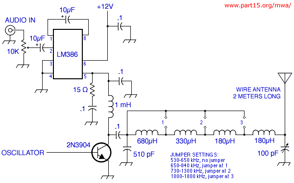
The circuit design is clever. An LC tank is connected to a 4049 CMOS inverter. The output of this oscillator is connected to the base of the 2N3904 transistor. Line-level audio input goes into an LM386; the output from the 386 goes through a choke into the collector of the 2N3904. Output is taken from the collector through jumper-selected inductors that tune the antenna to various frequency ranges. Unlike some other kits, the 1290K actually attempts to match its output stage to its antenna. This is part of the reason for the good sound quality.
(The comments below were posted in rec.antiques.radio+phono
and other newsgroups.)
It only took me about two hours to completely put it together. Our home is only one story, so your mileage may vary, but I get fantastic sound at 50 feet, so-so at 70, and about 90% static at 100 feet range. If that's within your tolerance, go for it.
It took some interesting tweaking (make sure you have a non-conducting screwdriver!).
-Curt Wiederhoeft
I've built and sold several of the Vectronics AM kits and they work great. The only problem I've had in building is some bad ceramic trimmer caps. Be careful soldering those as they can easily overheat and be ruined.
-Richard Mann
I checked it cursorily with a scope and its modulation is symmetrical and at about 85%-- although there does seem to be a supersonic component in the output, too.
Still, sounds pretty good, and the price is very right.
-Norm Lehfeldt
It used a regulated 13.8 DC power supply, but the range was limited to around 30-feet........so I got rid of it. I want 1/2-mile range and Vectronics is simply too weak for this. ;-(.
-Gaffo
My Vectronics can transmit up to 1/4 mile (tested it with my car radio). Something must be wrong with the one you have. BTW, I didn't like the AC adapter because it caused some interference, so I use a sealed lead acid Interstate PC12180NB 18 amp-hour rechargeable battery.
-r.t.
It gets downstairs alright, enough to completely close the eye tube on the Scott 800b. This radio has an usually wide AM frequency response, and the fidelity of this little transmitter is outstanding.
-Banjo Power
I just built one of these and it works well. I left the 10 mfd cap out as per manual and the line out on my CD player works good. A friend pointed out to me that you can install the frequency adjust variable cap the wrong way as two of the terminals are connected together. He did and his unit was dead. He found his error and it worked fine after correcting it.
-Lou deGonzague
C11 should be mounted so the two widest tabs (actually lead shoulders) on the capacitor body are closest to the board edge. Note that these are soldered to the ground foil on the bottom of the board...
For C12, the two wide leads are "parallel" to C9, with the narrow lead pointing to pin 8 of U1. If you trace out the runs, the narrow lead of C9 connects to pin 7 of U1.
-Uncle Peter
Tuning the trimmer caps in this kit is made much easier if you epoxy a small nylon wheel or roller to the trimmer caps. Wish I'd thought of that several kits ago!
-Richard Mann
Some specimens of the 1290K suffer from an audible buzz or a supersonic piggyback signal caused by parasitic oscillations in the power supply or in the oscillator section. (This is not the same thing as the 60 cycle hum that plagues many LPAM circuits.) Writing in rec.antiques. radio+phono, Werner offered the following tips:
1/ If you made your own power supply and are using a 7812 regulator, make sure you use a 0.1uf decoupling cap close to the regulator on the input and output. Without them the regulator may oscillate at very low levels and thus modulate your signal.
2/ The 4049 oscilator is somewhat unstable. It tends to vary the pulse width and or have ringing on the rising edge of the square wave it produces. This is transferred directly to the base of the modulating transistor & then appears superimposed on the transmitted signal. I effecively moved this "oscillation" to a higher (inaudible) frequency by adding a 220 pf cap in parallel to R4. This makes the unit quite useable. I suspect that a different 4049 would eliminate this problem or at least provide different results.
...Using Cmos gates to make this kind of oscilator has always been regarded as a short cut and not very reliable, by nature it is dependent on operating the chips in a linear mode which is not specificaly documented by the chip manufacturer. In short it is a bit of a kluge by nature.
I hope this helps anyone experiencing similar problems.
-Werner
A few specimens of the 1290K suffer from an overheating LM386 chip. Here are some ideas...
I've noticed the LM386 is quite hot to the touch...it's uncomfortable to leave your finger on it.
-Banjo Power
You could get some thermal conductive epoxy (the overclockers use it on PIIIs and P4s) and glue a small heat sink to the chip.
-Mike S
The voltage on the +vcc pin, which I think is pin 6, should generally be no more than +12V. If it's more, something is wired wrong, IMHO. If it's wired correctly, a bypass cap of about .01uf may help. Otherwise, it may be a bad chip.
-Bill Hutchinson
There are several versions of the LM386.
If your is a LM386M - note the last letter - the dissipation is only .73W. A LM386N is 1.25 W.
Along those lines, the best choice, if you can find it and are replacing your chip, is an LM386N-4 as it operates essentially the same, has the better dissipation, but tolerates 22v on +VCC.
-Prof F J Flutter
I have the 386N-1 -- what is its output?
-Gaffo
325 mW. Max. Vcc of 12 volts.
-Uncle Peter
If you're using a wall wart, be aware that those things will produce much more voltage than their ratings unless you actually draw the rated current... Verify the supply voltage. It may be higher than the chips are happy at.
-Robert Casey
If built according to instructions, the 1290K can work properly with an antenna up to 12 feet long. To use a longer wire than that, you would have to change the values of the components in the pi network.
If you are in the US and you are not on an educational campus, the Part 15 rules limit your combined antenna and ground lead length to 3 meters (which is equivalent to 9 feet and 10 inches).
Untested idea: The 1290K circuit board could be used as the basis for a similar but more stable and more powerful rig. A simple 1-transistor crystal oscillator, perhaps with a 1-transistor buffer amp, would replace the CMOS chip and its LC tank. (I would prefer to have a clean sinewave carrier instead of a parasitic-infested squarewave.) The 2N3904 would be replaced by something able to handle more power, perhaps a 2N3553. Instead of an LM386N-1, the modulator would be an LM386N-3 or LM386N-4. –Crash