Making A Pesudo-ECP Parallel Cable : Pictures Page 2
| Home | Making A Pseudo-ECP Parallel Cable | Page 1 | Page 2 |
Pictures Page 2
|
|
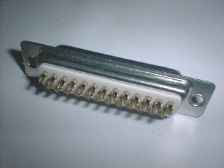
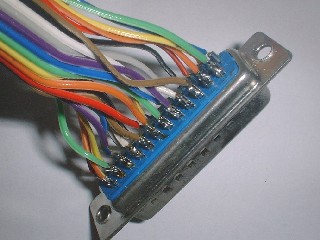
| Here is a picture of a typical DB25 connector, from the back. This is a DB25-female part. Check pin numbers and make sure wires are long enough before soldering. | On one side, connect the wires in a uniform arrangement. Be sure to make your own connection reference table. This will force you to verify everything, minimizing mistakes. |
 |
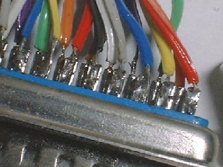 |
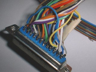
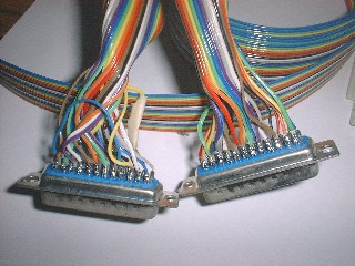
| The ECP connection chart must be followed for the other connector, shown above. It's a bit messy, but don't worry. Just follow your connection chart and solder the wires one-by-one. It's a good idea to do the data lines and the ground lines first. Note the jumper wire (in blue.) | A close-up shot of the soldered connections between pins and wires. It's not really a good job because I used too much solder. The key is to keep all the wire strands and solder globs inside the hollow of the pin. Don't leave a long exposed length of wire. The sheath should cover the wire almost to the connector. |
 |
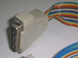 |
| The two connectors and the cable after completion of soldering. Now is the time to do visual inspection and electrical testing. | The pseudo-ECP cable, assembled after the wiring has been tested with PCs. Roll up the ribbon cable so that the housing closes properly. |
Go to the previous page or go back to Making A Pseudo-ECP Parallel Cable.
| NFPT Program and Site Copyright © 2002,2003 K.H. Man all rights reserved |