Making A Pesudo-ECP Parallel Cable : Pictures Page 1
| Home | Making A Pseudo-ECP Parallel Cable | Page 1 | Page 2 |
Pictures Page 1
|
|
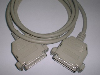
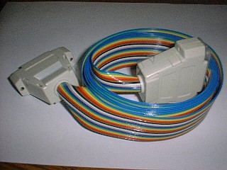
| This is a null modem cable. | This is the finished pseudo-ECP parallel cable. |
 |
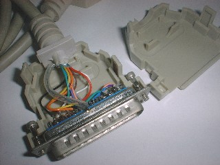 |
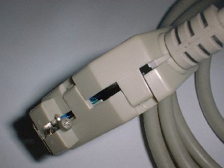
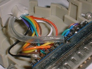
| This picture shows how the plastic housing joins together. Note the opposing clamps. It is designed to be difficult to open. Most casual attempts at opening the housing are foiled. | Inside the housing of a null modem cable. Many such cables have 12 wires, and good cables have grounded shielding (the braided wire inside the thick transparent sheath.) |
 |
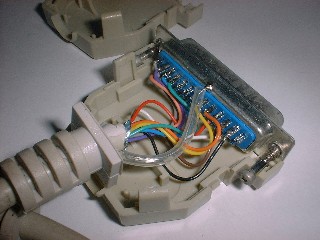 |
| The EMF shield is connected to the metal part of the connector. A standard null modem cable should never have a signal pin on one side connected to the same pin on the other side. | Another view of an opened connector housing. Familiarize yourself with the pin numbering and wire connections first before commencing to desolder the wires. |
Go on to the next page.
| NFPT Program and Site Copyright © 2002,2003 K.H. Man all rights reserved |