 |
|
|
|
|
|
|
|
|
|
|
|
|
|
|
|
|
|
|
|
|
Building a Preselector |
|
|
|
Home Next |
|
|
|
|
|
If you thought about building a PRESELECTOR, but have hesitated - and if you are fairly competent with hand tools, soldering, and electronic assembly - then now's your chance to build your project right along with me. I plan to put in some time on this almost every weekend. So here is week #1 on this page #1. |
|
|
|
 |
|
|
|
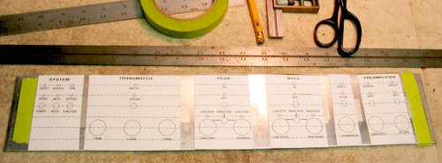
This is my design layout. I made it flow logically from left to right just as the circuit flows. I elected to use a 1/8" thich, 19" aluminum rack panel (3.5" high [2RU]). You will have to decide on the cabinet, face plate, and size that suits your taste. Remember: Cosmetics are everything! Once this thing is finished, you are going to have to look at it for a long time. So give the layout a lot of thought. Later on, I'll show you how I make the decal that will be glued to the panel. At that point, you can choose the colors, letter sizes, and all the other graphics. You will also want to give some thought to the style of knobs that you find attractive. My layout is based on 3/4" knobs with 1.5" between them. I positioned everything full size using a graphics program. Pagemaker is great for this, but unless you are in the publishing business, better think about a less expensive program, or just use a pencil and ruler. Once all the modules were layed out, I cut them and taped them to the panel so that they could be moved around and positioned in a pleasing and functional way. |
|
|
|
 |
|
|
|
Once I had everything positioned to my liking, I turned the panel over and covered it with "label stock" which is nothing more than peel-n-stick paper (note the 1" margins at each end for the rack mounting flanges). Now, with a clean surface, I transposed my design to this side using a square and machinist's ruler. The entire grid is very accurately layed out as a 1/4" pattern. This will become very important when we get to the decal label phase. So use a sharp pencil. Note that each of the five "modules" has a black stripe seperating it from its neighbor. Also note my propensity to have all the controls on the same centerline, as are the toggle switches and the LED indicators. I like ergonomic equipment - good logical layout - it should be useable even in a dark room.
Now all the markings can be center punched in preperation for the drilling process. The holes will be drilled as follows: T1-LEDs = 0.110"; pots and rotary switches = 3/8"; toggle switches = 1/4".
I am not going to use mounting hardware for the LEDs. The .110" hole (or 1/8" if you must) is fine for rear mounting the LEDs with a drop of anerobic or cyanoacrilate adhesive (Super Glue) or something similar. The panel is 1/8" thick so the LEDs will penetrate just the right amount. At this point, I suggest "living" with the design for a few days. Imagine it in operation. Is everything in an intuitive location? Will the finished panel look professional? Will co-residents like seeing it on your radio desk? Okay, when you think you are ready ... drill and debur the panel. |
|
|
|
 |
|
|
|
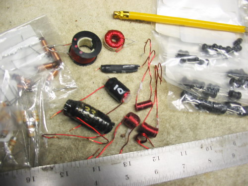
Here's a snap of some of the homebrewed inductors I made. You can buy the ones you need, but i am a fiddler and, besides, I already own an LCR meter. There are links from the schematic page where you can get these things and the typical values. If you choose to use my design, you'll need 12 of them - I never paid more than $1.00 (US) each for these and most of them were about $0.65. |
|
|
|
|
|
Last day my wife let me work on this: Jan 8, 2006 |
|
|
|

|
|