 |
|
|
|
|
|
|
|
|
|
|
|
|
|
|
|
|
|
|
|
|
A "SOUP-UP" Project:
MFJ-956 Passive Preselector |
|
|
|
Assembly
Photos
Home |
|
|
|
|
|
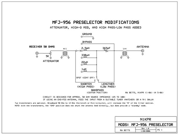
If you own, or are about to own, the MFJ-956 passive preselector, here are three simple modifications,
which will make this device considerably more flexible and a valuable asset for the feeding of your receiver.
This project is a good alternative option to building the real Betts Preselector featured elsewhere on this site.
It works well and allows the ability to make further mods or experiments. |
|
|
|
 |
|
|
|
The stock preselector, with a source impedance and load impedance of 52 Ohms will tune in the following passbands:
Switch Frequency
Position (min / max)
3 200 KHz - 1.0 MHz
4 600 KHz - 3.0 MHz
5 2.5 MHz - 10.0 MHz
6 9.0 MHz - 35 MHz
Measurements are close-approximate and
will vary with terminal impedances.
S1 = SPDT center off
(Single pole / double throw)
(The pot is carbon composition type, deposited, or film. Do not use wirewound) |
|
|
|
Final Testing: (added 01 June 2006. By bench testing and actual usage I have determined that the 4:1 transformer option is probably not desirable for most users. The coils that MFJ uses are rather low-Q and do NOT function very efficiently at the lower frequencies. I experienced as much as 12dB loss in the BCB and less loss above 3-5MHz and up to 20MHz. Above 20MHz the 956 is of questionable utility. However, for the maximum Q and filter response sharpness, the transformers are necessary. This is the kind of compromise that happens when less-than optimal components are used in the basic design.Their use is a value judgement based on what application the unit is going to have for you. Of course, the transformers could be switched in or out via a 4PDT switch (maybe mounted on the back of the unit).
*** More to come, as necessary. *** |
|
|
|
|
|
Note that when the function switch is in the "Bypass" position, the "Attenuator" is still active.
* S1 is a center-off toggle switch (a 3 position rotary switch may be substituted).
Modes are:
Shorten the electrical length of the antenna circuit.
Lengthen the electrical length of the antenna circuit.
Resonate the entire antenna circuit to a variable bandpass frequency.
This second phase mod adds two 4:1 RF transformers at each SO-239. Wire the transformers so that the 52 Ohm side is facing out and the 12 Ohm sides are facing in towards the preselector's circuitry. Be sure the transformers you select have a bandwidth rating suitable to your needs (Ref: Mini Circuits and Coilcraft).
The 12 Ohm internal impedance will increase the "Q" of the bandpass filter and tighten up the bandpass skirts considerably.
NOTE: You may just do a partial mod and not utilize the 2 transformers. In that case, add a 470k Ohm resistor from the "antenna" jack to ground to provide a constant static bleed. |
|
|
|
This is a tinkerers project and will void the warranty with the manufacturer. Don't go where you don't belong when working on electrical devices or using power tools. If you are not comfortable using soldering irons or power tools, find someone who is. Wear appropriate eye protection and be careful to not burn the cat with the soldering iron. All other disclaimers, cautions, and warnings apply -- please use common sense and good judgement. Enjoy this hobby; it's very rewarding. |
|
|
|

|
|