 |
|
|
|
|
|
|
|
|
|
|
|
|
|
|
|
|
|
|
|
|
|
|
|
|
Preselector Page 1 Go to: Next or Page 1A Page 1B page 2 page 3 page 4 page 5 Home |
|
|
|
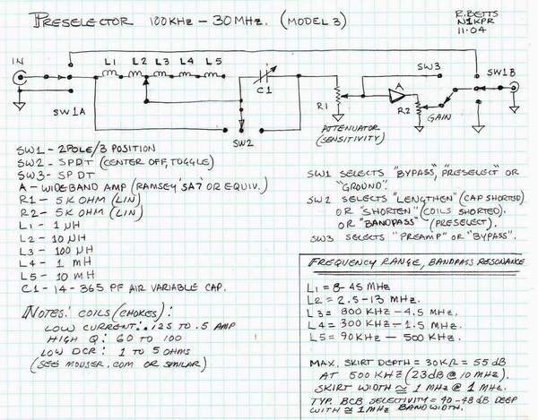
Although this is the second version of an on-going R&D project, it still represents the basic design principles.
The circuit is fairly straight forward and really shouldn't need any explaination:
But, here's the basics:
1. Cap in series with your antenna makes ir electrically shorter.
2. Inductor in series with your antenna makes it electrically longer.
3. Cap and coil in series equals zero impedance at resonance ( C x L = a passband filter)
Subsequent improvements and fine tuning upgrades have been added to the circuits below. |
|
|
 |
|
|
|
|
|
|
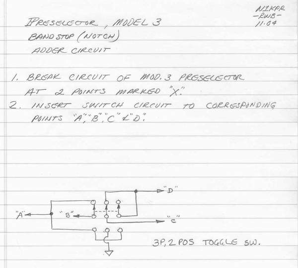
The very same series resonant circuit connected between the line and ground would provide a "band stop" or notch filter. The above schematic does not show points A, B, C, and D. If you break the line between SW1A and L1 and call the left side "A" and the right side "B" then break the line between C1 and the Atten pot and call the left side "C" and the right side "D," you can then connect the mode switch, at left. Switch "up" is bandpass filtering, switch "down" gives band stop (notch).
This arrangement works fine, but it limits you to either the bandpass or band stop functions. |
|
|
 |
|
|
|
|
|
|
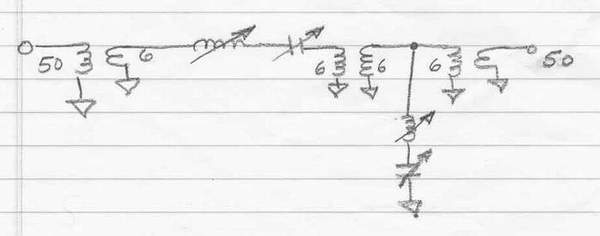
This next schematic shows two additional improvements:
1. The bandpass and notch functions are available full time. However, to do this, they had to be electrically isolated. Instead of using active isolation ( a unity gain transistor stage) I elected to use interstage transformers (Micro Circuits or Coil Craft). Note that the L and C components have been graphically simplified for ease of explaining this circuit. In reality they must be just the same as those in the top schematic.
2. In order to increase the selectivity of both filters, B/P and notch, I decided to reduce the circuit impedance by a factor of 8:1, or 6 Ohms.
The results are as expected with an effective selectivity of +/- 5 KHz, or a total skirt width of 10 KHz.
This is not as sharp as a crystal or mechanical IF filter, but very effective on the crowded bands...even very usable on AM broadcast!
Bottom line: Since the bad stuff is attenuated and the good stuff is passed at unity levels, you get the benefit of having a circuit with gain, even though this is a passive device. |
|
|
|
|
 |
|
|
|
|
|
|
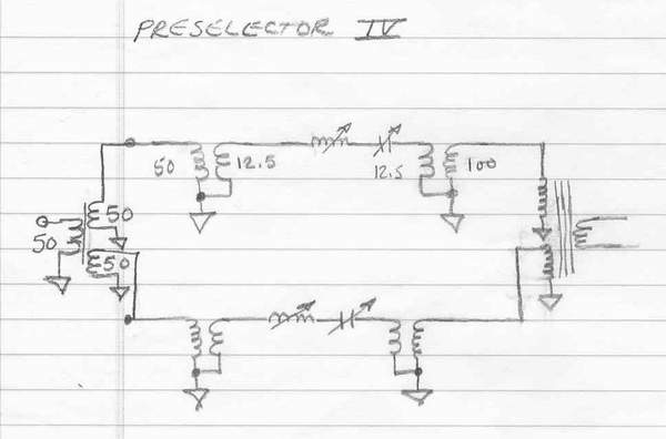
This schematic speaks for itself. it's the next phase of this evolution.This circuit allows two bandpass filters to be superimposed or slightly offset from one another. Now you will have adjustable selectivity level along with adjustable bandwidth. Of course, you'll have to incorporate all of the component switching and attenuators as in the top schematic. Then, when you are done with that, add the notching feature...viola. |
|
|
|
|
 |
|
|
|
|
|
|
I don't have the space here to describe how to use a bandpass and notch filter...it's pretty much instinctive: peak what you want, notch the undesirable stuff. Note that if you tune both filters to the same frequency, you create a very large attenuator...that's a good way to calibrate the circuit if you are so inclined. You really have to "play" with the controls for a while until you get a "feel" for the operation. But you'll wonder how you ever got along wothout a preselector...once you've used one! |
|
|
|
|
 |
|
|
|
|
|
|
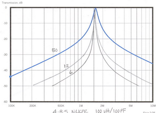
The evolution of preselector technology:
The two schematics above make use of lower "internal" impedances, within the circuit. Here is a response plot of the filter tuned for the high-end of the BC band with different source and load impedances. Note the increase in "Q" between 50, 12, and 6 Ohms as taped from the interstage transformers. From a practical standpoint, the 6 or 12 Ohm circuit is about a tight as it's going to get without going to active stages (and their associated problems). The next, and probably last phase of this project will be adding a series resistor in the form of a potentiometer which will allow "Bandwidth" control which is represented by the 6 Ohm and 50 Ohm limits of the circuit. |
|
|
|
|
|
Go to the next page to see how I package these things. |
|
|
| NOTE: If you don't want to bother finding all the components, punching a chassis, wiring everything, and making the face plate pretty, the just go out and buy an MFJ-956. It's a new product that bears a strikingly similar circuit to my original preselector from 1993. Dare I flatter myself that MFJ saw many of my circuit postings and...awww, never mind. Anyhow, the MFJ does work, if only in the most pedestrian form, but it does offer a nice platform for you to add to, like an attenuator, preamp, notch filter...well, you get the idea. |
|
|

|
|
|