Motorcycle cylinders work quite independently compared to automobiles. Separate carburation, intake manifolds, exhaust pipes and sometimes even independent air filters allow the cylinders to be tuned so that one may be making more power than another. This can be due to differences in air flow, temperature, injection, or valve adjustment betwen the cylinders. Periodically, the cylinders should be synchronized. This is usually done by comparing intake manifold vacuum beneath each throttle and trimming the mixture until balanced.
Some old-timers will tell you it can be done by ear, listening to the air flow in each carb throat through a tube stuck in your ear. Most modern tuners have switched to mercury sticks. Rigid tubes stuck in a bath of mercury are attached to the vacuum source. The vacuum draws the mercury up the sticks in proportion to pressure difference between the manifold and the atmosphere. In order to smooth out the individual vacuum pulses, a damping device is needed. This is nothing more than a small orifice (pin hole) restriction in the lines, placed close to the manifold with an air reservoir (length of tube) behind it. Because there is no real air flow in the gauges, there is no pressure drop across the orifice. But when the manifold vacuum drops there is a delay before the gauge pressure can bleed off and it appears steady and readable. Other types of vacuum gauges include mercury-less versions (that draw metal rods), or traditional needle, or "clock" gauges. The clock gauges are very fast acting (they are designed that way so you can see engine problems such as sticking valves). You will definitely need a damper if you choose a clock gauge. I would recommend using two side by side gauges for checking cylinder synch. The reason is, the cylinders are not perfectly independent. As one cylinder drops strength, the idle drops, and this will change the vacuum in the second cylinder's manifold. It takes a bit of fooling around to get a cause-and-effect feel when you are turning the screws. Swapping gauges would make this difficult.
|
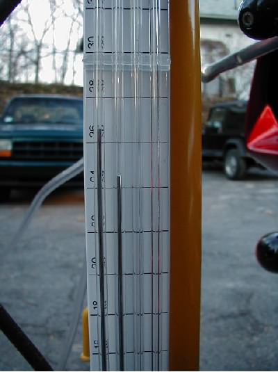
A cheap set of carb sticks. Marked in centimeters of mercury, these are very sensitive. Most manufacturers request balance less than 2 cm Hg. Up to four cylinders can be viewed side-by-side. |
The Falco control unit uses manifold pressure as one of its primary map variables (especially at idle). You would like to synch the cylinders with this control "open loop" so you will need to unplug the electrical connector from the manifold pressure sensor. This sensor is clipped to the lower left side of the airbox. Attached to this are two very small vacuum lines, connected between a "tee" connector and each of the manifolds below the throttle body. These should be unplugged from the tee. You can use them as a vacuum source, or you can plug them. You will need very small adapters to attach these hoses to most vacuum gauges. I found suitable conical shaped adapters in my Mitivac vacuum test kit.
| On the left side of the airbox, unplug the electrical connector to the manifold pressure sensor. Also, remove the two vacuum hoses from the "tee". Test vacuum may be taken off of these. Or plug them. | 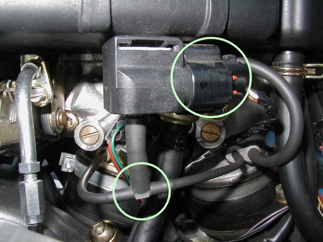 |
On the right side of the intake manifolds, there are larger vacuum ports. The front port is plugged. The rear is attached to the clutch diaphragm. You can use these for test vacuum and they will fit most gauges easily. The clutch line uses Aprilia's favored clic-clamp. You may not be able to reuse this clamp if you remove it. Plan on having a 1/4-in worm clamp on hand.
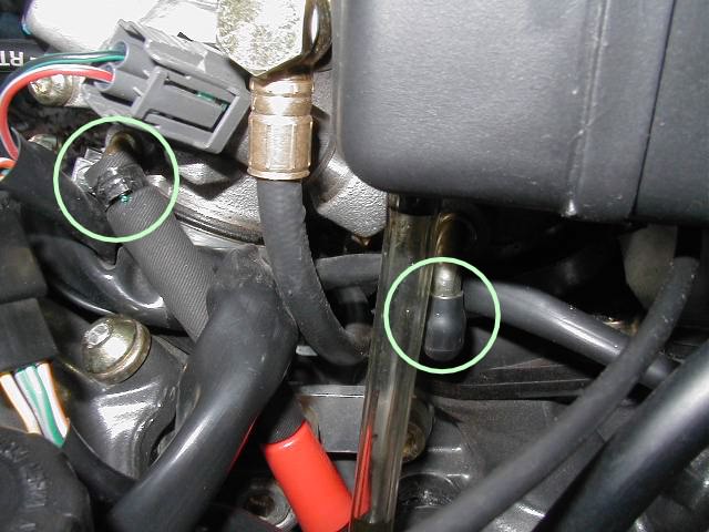 |
Larger vacuum ports are on the right side of the intake manifolds. The rear line feeds the slipper clutch. Depending on how you remove the clamp, you may not be able to reuse it. |
| Attaching the gauges to the left-side vacuum lines. Note the adapters and damper orifices in the lines. | 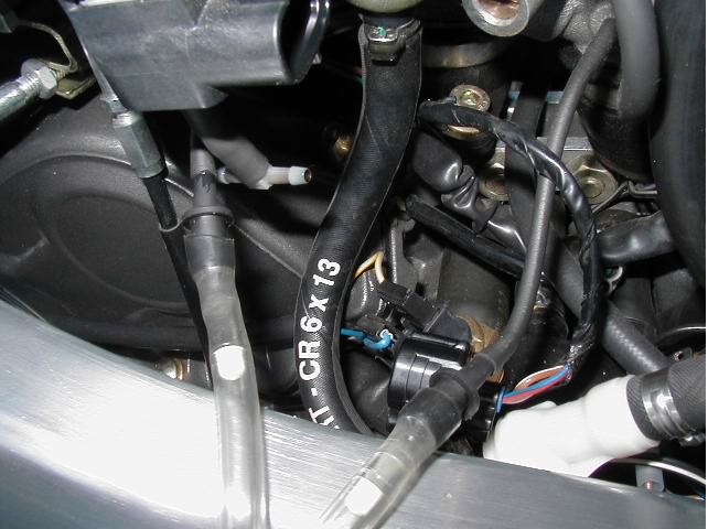 |
You'll want to adjust the cylinders while warmed up, but if you plan on idling for an extended time, you may want to put a fan in front of the bike. You can start the bike up and idle it with the gauges in place, but remember never to rev the throttle on or off quickly with the sticks attached. It is possible to suck mercury out of the gauges and into your engine. Before starting your bike, though, locate the brass air bleed screws on the left side of the throttle body. Mark the slot location, then turn the screws lightly all the way in, counting the turns. Turn them back out to their original location. Record the number of turns so if you get messed up you can get back to where you were.
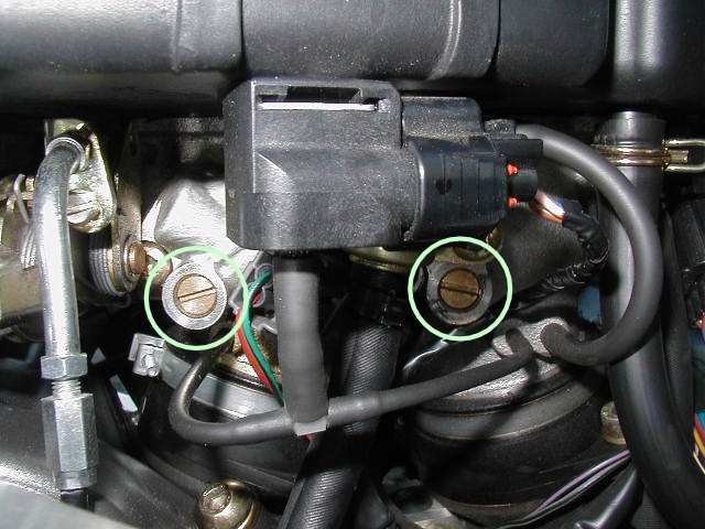 |
The mixture is trimmed with air bleed screws. Clockwise closes off the orifice, making the mixture richer. Count the number of turns to seat the screws before you start working. From the factory, these screws are usually set an equal number of turns out (approximately 1-1/4). |
If you are working for the EPA, you'll want to see how lean you can possibly set these screws and still have the bike idle without overheating or stalling. For the rest of us, the tuning theory is to richen these screws (turn clockwise) until doing so no longer results in a better idle. Better idle, loosely defined, is a faster idle speed and a steadier vacuum. Your secondary objective is to balance the vacuum in the manifolds for each cylinder. While you do this, you will want to keep the idle speed around 1,300 - 1,500 rpm. Balancing at too high an rpm accentuates differences in port flow. Adjust the idle speed with the thumbscrew on the right side frame. Note that the thumbscrew and idle screws do the same thing: control the amount of air in the mixture. So, many different "solutions" of air screw settings and idle screw settings are possible (not to mention the CO adjust screws in the ECU box). Driveability will dictate the best settings. Normally, that is around 1 to 1-1/4 turns out on the air screws and the idle adjust thumbscrew near its lowest possible setting (it will stop reducing the idle when the throttle plates hit the second idle stop). If you are running a Factory Pro or other aftermarket chip, you may find that lower air screw settings and more throttle plate opening are necessary for good off-idle throttle response. See the idle adjustment page for hints in this case.
I can only suggest a tuning procedure here, as I haven't read the manual on this. I ended up with the front screw out 1-3/4 turns and the rear screw out 1-1/4 turns. So a good starting place would probably be with both screws 2 turns out. Richen up a quarter turn at a time until the idle drops. Eventually, it will drop noticeably. When it does, back the screws out 1/4 turn. Balance the cylinders from there, by turning the strong cylinder's screw out. Watch the vacuum gauges. If the vacuum is erratic, as if searching for an idle speed, try leaning out another 1/4 turn. My bike never did have a really steady vacuum when balanced, but seemed to run better with the front cylinder slightly stronger. I've been told this is not abnormal.
When you are done, reset the idle speed and reconnect the vacuum lines and electrical connector.
Update: August 2001. A Mille owner from Australia was good enough to send me a copy of the Mille service manual for the cylinder synchronization procedure. In summary:
Go back to the Falco home page.