Marc Salvisberg at Factory Pro tuning has put a lot of time and experience into a new chip for the Falco/Mille. It pulls very hard midrange to top, but I especially appreciate the time he put into making the low cruise rpms smooth. The first thing most people notice if you use this chip is that the idle speed comes up significantly. There is usually not enough range in the idle adjustment thumbscrew to bring the idle down! As Marc says, funny things happen when you give an engine the right amount of fuel for the throttle settings.
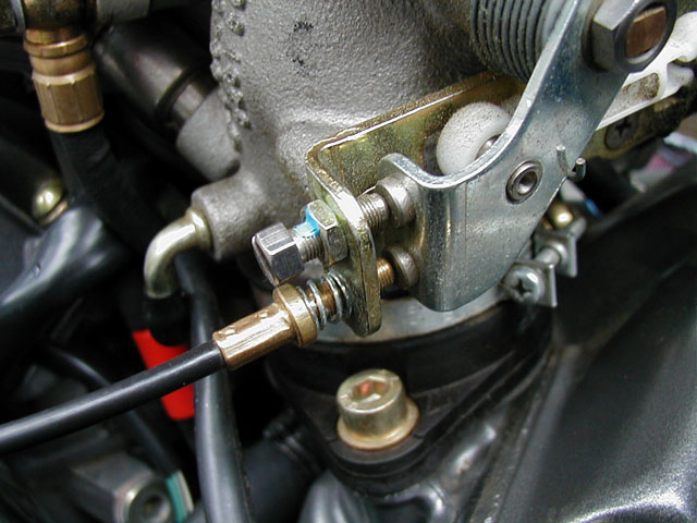
On the right side of the frame rail is a thumbscrew for adjusting the idle stop. This idle stop determines how far the throttle plates are open when they are in their closed position. Turning the thumbscrew counterclockwise will reduce the idle until a the throttle linkage hits a second idle stop, hidden under the airbox and set by the factory. You can remove the airbox and adjust this factory stop to lower the idle further, but driveability will suffer. As the throttle plates approach a sealed position, the off-closed throttle response gets jerky. If you have moved this factory stop, it can be reset by turning it out until the throttle plates are just completely closed, then turn it in between 1/2 and 3/4 turns. Tighten the M5 locknut when you are done.
| The lower throttle stop screw is connected via flexible shaft to a thumbscrew on the frame rail. a spring holds tension on it. The upper throttle stop is set at the factory, 1/2 to 3/4 turns in from the position where the throttle plates are completely closed. A locknut holds it in place. |
|
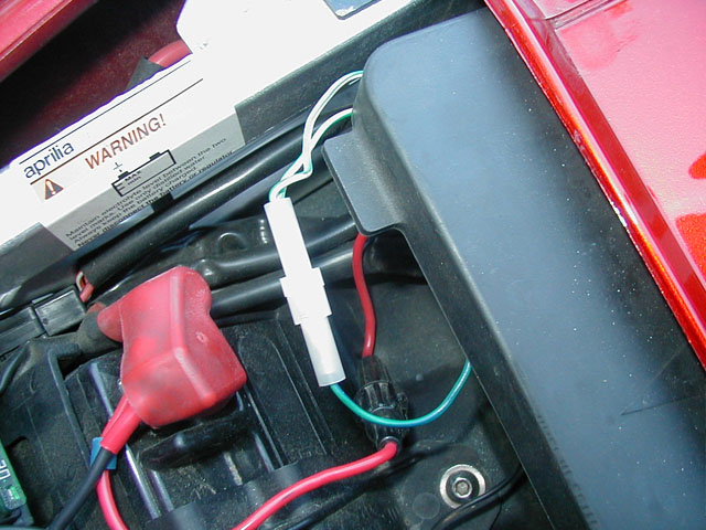
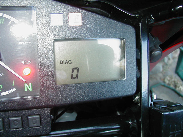
From the factory, the throttle position sensor (TPS) is zero'd to the value of this secondary throttle stop. If you have lowered the throttle stop, the TPS adjuster will now have a negative offset, but this is a small problem as the primary map at low throttle openings is vacuum axis and not throttle position. You can verify the correct setting of the TPS removing the seat and removing the rubber cover on the ECU protection box. There will be two mating barrel connectors, unplugged in the rubber box. Plug these together, then turn on the key without starting the bike. When the throttle plates are closed against the throttle stop, the computer should be reading the TPS potentiometer as "0" (look at the right-hand dash display for a "-1", "0", or "1" indicator). If the dash display reads "-1", your TPS has a slight negative offset, and you should should pick up the idle stop a bit until it reads "0". If it reads "1", your TPS is not adjusted properly. It is likely that your idle stop is a hair too high. Try readjusting it lower, but staying in the 1/2 to 3/4 turn range. If the TPS display will not come down to "0" in this range, the TPS can be reset by loosening the mounting screws and rotating the potentiometer. This is very unusual, however, so be sure you've not made a mistake before moving your TPS from the factory position. Turn off the bike and unplug the diagnostic connector when you are done.
|
The diagnostic connector is located in the rubber ECU box. Plug the two connector halves together with the engine off. Turn on the key (without starting the bike) and the computer will enter diagnostic mode. |
| Unlike many other bikes, you don't need an ohmmeter to set up the TPS. In diagnostic mode, the computer will tell you where it thinks "zero" throttle position is. |
|
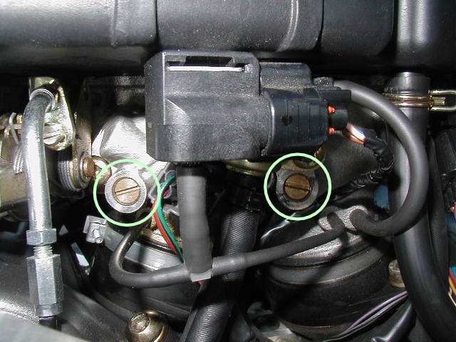
With your throttle plates set and TPS verified, you can now set the idle mixture for the desired idle. There are two inputs left, the air bleed screws and the CO trim pots. The air bleed screws control the amount of air bypassing the throttle plates. There are two of them so they may be used for synchronizing the cylinders. These are the large brass screws in the base of the throttle bodies, visible from the clutch lever side of the bike. The goal is going to be adjusting the idle speed by moving these screws. Stock, they are approximately 1-1/4 turns counterclockwise from fully seated. With the Factory Pro chip, they will need to be approximately 1/2 turn out to get good driveability.
|
The mixture is trimmed with air bleed screws. Clockwise closes off the orifice, making the mixture richer. The stock setting is about 1-1/4 turns out from fully seated, but the Factory Pro chip will require that these be closer to 1/2 turn out. |
Lightly seat the air bleed screws (clockwise), then turn them out one turn counterclockwise. Start and warm the bike above 176 F (80 C). Turn the screws clockwise equal amounts until the idle drops to your desired range, but the idle is still smooth. The factory idle setting is 1150 - 1350 rpm, but I have not been able to get my bike to idle smoothly below 1500 rpm. If the idle drops off sharply, you are probably too rich and should back the screws a bit.
With the Factory chip (and some other aftermarket chips), the CO pots are enabled. These are located in the metal ECU box, and can be accessed through holes in the front next to the connectors. These are 1 turn potentiometers, nominally centered in the middle of the range. With USA stock chips, these pots are disabled in software. With the Factory Pro chip, they are enabled, and should be adjusted for best idle.
If you like, you can also synchronize the cylinders at this point. The more I fiddle with this bike, the less important I think exact cylinder synchronization is. In fact, the service manual emphasizes trimming the screws to synchonize CO emissions, and verifying vacuum only to see that it is in the correct range (22.5 cm Hg, plus or minus ten percent). I have found the bike runs a bit smoother with a "stronger" front cylinder. See the procedure for setting up the vacuum gauges and synchronizing cylinders if you wish to verify your vacuum balance.
Go back to the Falco home page.