Deep 68k:
How to Build an Automated Checkers Player in 21 Days
ECE341F
Design Project
Andrew Brzezinski
Sameer Khushal
Introduction and Motivation
The main goal of the project was to build an automated checkers player against which a human could compete. The robot consists of a mechanical component that physically moves pieces corresponding to both human and computer moves. As well, there is a software component that verifies the validity of human moves, and also determines which moves the computer should make.
The reason that this project was chosen was due to the challenge that it posed. A full system capable of playing and defeating a human player would mimic the results that were demonstrated by IBM�s Deep Blue machine. After beginning the project it was found that a similar project was assigned to the Engineering Science students several years ago, for their term-long design project. Hence, the challenge made the project worthwhile.
Description
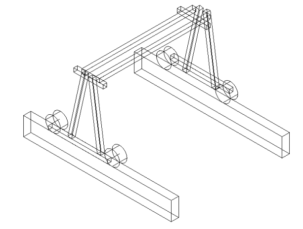
To summarize, the mechanical system of the robot locates an appropriate piece, picks it up, and replaces it at a different location. This system required a complicated and detailed design. The game was based on basic checkers rules. Referring to the board layout of Fig. 1, game pieces need to be moved between blocks of similar colour. This was implemented using a gantry for motion in the y direction (indicated in Fig.1), and a car attached to the top of this gantry for motion in the x direction. A claw mechanism was attached to the bottom of this car. The car and gantry provided all of the necessary motion to locate the claw over any position on the board. To actually pick up a piece from the board, vertical motion is necessary. Two options arise for this issue: either the claw is moved to pick up the piece, or the whole board is elevated appropriately to the claw. We opted for the elevator, in order to reduce the amount of weight that the gantry had to carry. Otherwise, an extra motor would be needed to raise and lower the claw.
The gantry is driven by a motor in the indicated y direction, while the car drives itself along tracks on the top of the gantry. A wireframe picture of the gantry is found on the title page of this report. As well, Fig. 2 depicts the car. To actually stop the claw over a specific position, two light sensors are used in conjunction with 2 banks each consisting of 8 high intensity LED�s. The circuit in Fig. 8 powers the LED�s. Each LED is centered over a square of the checkers board and equally spaced from adjacent LED�s (3 fundamental LEGO units). One light sensor keeps track of the position of the gantry relative to the fixed bank mounted on the side of the board (see Fig. 9). The other keeps track of the car�s position relative to an identical bank of LED�s mounted on the top of the gantry. Fig. 3 depicts the side view of the gantry; note that as the gantry moves from side to side, the light sensor will detect the LED�s. Fig. 4 shows the motion of the car along the top of the gantry. It also shows the location of the second bank of LED�s. By locating the light sensors over different combinations of LED�s, 64 unique positions, corresponding to a standard checkers board, are accessible by the claw.
The claw mechanism is quite a simple device: it is an arm that swings back and forth radially to an open or closed position, controlled by a motor (see Fig. 5). The elevator is the final mechanical system used. The elevator system consists of two individual elevation devices. Each one is based on a car almost identical to the one used on the gantry, except the car is vertically oriented. Each elevation device is located at an opposite end of the board (Fig. 9) and connected by beams across that distance. On these beams the actual checkers board is fixed. The elevation devices are connected in parallel; this enables the board to be moved upwards and downwards as required. See Figs. 6 and 7 for the elevator.
The algorithm for the machine is described by the following flowchart:
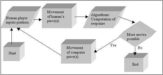 |
See Appendix B for the robot�s code. There are two main components to the algorithm implemented for this robot:
- hardware control
- checkers algorithm
The hardware that was interfaced were two light sensors, and five motors. These were managed by the hardware control algorithm. One of the notable aspects of this code is the manner in which the board locations are stored in registers. Since each board position has a unique letter and number combination (e.g. A1 - see Fig. 1 for board layout), both of these ASCII values are actually stored in the same register, with the letter located in the first 16 bits, and the number in the other 16 bits. The human player enters the values for his/her move on the keyboard; this is read in by the computer using polling. The gantry and car motors are controlled based on start and destination position values passed to the hardware control algorithm by the human or by the checkers algorithm. The algorithm calculates the displacements required by both the gantry and the car and turns on motors accordingly. To find a board location, it is necessary to monitor the light sensors and to keep track of the claw�s current position. The sensor signals are read by polling.
In designing the light-sensing algorithm, it was necessary to debounce the sensor�s output signal (as shown in Fig. 10). As well, it was found that regardless of the sensitivity level of the sensors (controlled by the LEGO board), they would cause motors to stop at the edge of the light beam (Fig. 10). This means that depending on the direction the car or gantry approaches a light from, it will detect the high intensity light with an error of approximately � centimetre. Although, this is not a large distance, it may become significant because the exact destination position of a piece is not fixed. Pieces may start to interfere with each other or the claw may miss them entirely when this error accumulates. The solution to this problem was to implement a delay algorithm that waited sufficiently long until the sensor was centered on the light.
The checkers algorithm was reduced in its functionality due to time and testing constraints. It did not allow for kings or double jumps, although the mechanical system was ready to comply. The algorithm basically queries a matrix representing the current board status. However, it goes far beyond picking the first available move and making that move. The algorithm considered the following possibilities (in order of decreasing priority):
- prevent a computer piece from being killed;
- kill a human piece;
- find a safe position to move to;
- find any position available; and
- no positions are available so the game is over.
For each of these possibilities, each position on the board is queried for a computer piece. If a computer position is found, the possible destination positions for this piece are considered. If a destination position satisfies the possibility currently being considered, then the computer algorithm tells the hardware control algorithm to implement the move to this destination position. In addition, each of these priority possibilities has two further criteria: consideration must be made of pieces on the boundary of the board, as well as pieces inside of the boundaries. This is implemented by careful testing of boundary conditions on positions being queried.
Results
The project worked very well, and exceeded expectations in some areas. Aside from a few errors in the checkers algorithm, the robot was fully capable of playing a game of checkers against a human player. The mechanical system worked perfectly, and as of the final lab period, the computer was responding to human moves. The only problem seemed to be that the computer didn�t update the board position in memory properly after a move was made.
We were faced with many problems in developing this project. A major problem was the lack of parts available to build the entire mechanical system. This was overcome by supplanting the parts with our own LEGO. We were forced to learn quite a bit about building mechanical systems: often, designs had to be modified or completely rethought due to friction, torque, the interaction of gears and motors, or a combination thereof. Another major concern was with having the claw being able to repeatedly find specific board positions without having to be reset to a standard position. This was dealt with by using light sensors to search for LED�s marking board locations (as described earlier). The entire checkers algorithm seemed at first to be an overwhelming endeavor. However, the use of modular code and thinking of steps individually soon made the algorithm attainable. In general, the whole project was dealt with as a large number of smaller projects. Each individual part had to be completed efficiently and quickly in order to satisfy the strict time constraints.
If we did it again�
In retrospect, we find that a new design idea may not be as feasible as a proven method, especially when time is a major factor. Specifically we encountered this in building the gearing systems to run the motors. It was found that only certain combinations of gearing systems were compatible with the electrical characteristics of the motors. The solution to this problem was to use designs that were supplied in the design books for gearing systems, and modify them to suit our needs. This enabled us to spend valuable design time on the optical subsystem.
At the end of this project, we were very satisfied with the results and the progress we made. Mechanically, the robot did exactly what it should have without any problems. In terms of software, the algorithm could only be made "smarter", by adding more levels of strategy. Time was the only factor with respect to that. We are very happy with our implementation as it met or exceeded our expectations in several areas. The effort that we put into it satisfied us that we performed to the best of our abilities.
Concluding remarks
Overall this project was a very worthwhile experience. It taught us to be efficient in terms of time budgeting, and organizing a well thought-out plan for the design. One of the most valuable aspects of this design is that it can be made to play virtually any board game, given the appropriate game playing algorithm and the proper arrangement of LED�s.
The motivation of the project was met by demonstrating that it is possible to build a device to play checkers against a human opponent. Using the myriad of processors available today a portable version may be made that would enable the design to be a viable commercial commodity.
Appendix A
(gzip file containing postscript document, 139kb, 3 pages)

This page is maintained by Sameer Khushal.