| Electrics - dials, gauges and burger vans |
| Wiring Loom The whole of the front end of the loom had its protective covering removed, you will find that after 30 years in a hot engine bay, it becomes very dry and brittle, the good news is that that is what it is there for and it should prevent the same thing happening to the wires themeselves. Any damaged wires, typically damage to the outer covering or frayed connections, should be replaced. When replacing wires work through systematically and only attempt one at a time! New spiral wrap has replaced the protective covering. Quick, cheap, easy and efective. |
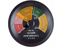
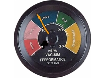
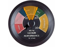
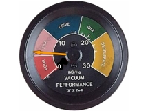
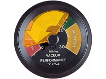
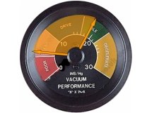
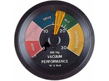
| Gauges There are a number of gauges missing from the consol of the 96, some more importnat than others and of personal choice. The purpose of gauges are to monitor the condition and performance of the engine - somethting particulalry worthwhile if you have spent a lot of time and money on building a performance engine. Tachometer - of all the possible additional guages available, this is the most important. simple to install, this guage monitors the rpm of the engine, or rather, it enebales you to identify rpm ranges of usable power or rpm ranges where problems may be occuring. Oil Pressure - Increasing an engines performace, or expecting a lot of an engine requires an excellent lubrication system. I have replaced the oil pressure relief valve spring with one from a ford V6 Taunus. Increased oil pressure should ensure more oil is getting to more places - I want to know that I have a nice high oil pressure. Oil Temprature - Not often included on a standard guage cluster; as well as lubricating, oil also cleans and cools. Cooling is an essential feature but has its limits and when the oil is getting too hot, it can fail to help cool the engine and its viscosity increases beyond an effective point. Vaccum gauge - the downward movement of the cylinders, when the inlet valve is open, is what draws fuel, through the carburettor and into the engine. On a 96, it also drives the vacuum advance unit on the distributor. The strength of the vacuum can in itself indicate the condition of the engine. More than that, the movement of the dial can also allude to other potential, hidden, defects with the engine: Vacuum Diagnostics All of this I got from Jack Ashcraft and his book, Total Performance V4 - go get a copy, for information on this and a whole lot more. The movenet of the vacuum guage needle can tell as much about the condition and performance of the engine a the position of the needle. Behold... |
| Remove the dashboard. Failry simple to do. It is held in place with screws around its edges and in the centre along with the ventilation switches. Remove the guages and switches. Make a note of there all the wires go or - as I did - take lots of phots with a digital camera! Remove the top cover, glove box and glove box lid bits and peices. Keep them safe! Source some suitable material to make you dash from. A 1' x 4' sheet is ideal and just the right size for a cheap offcut as the standard sheet metal size is 8' x 4'. As I have a nice retro Moto Lite alloy steering wheel going in, I thought a nice sheet of steel would do the trick. I don't know why but for some reason 'Circle Polish' spoke to me. It said "mmmm. Barbarella....1970s motorsport.... " and now I have started on it, it is saying "mmm? Home made time machine?" And considering I got hold of it from a chap who makes burger vans, the doubts are really beginning to creap in! Cover both sides of your sheet metal with masking tape. Using your now bare and surprisingly basic dashboard as a template, draw around it. Draw in the two large holes for the main guages, a rough outline of the glove box hole, the position of the ventilation sliders and all the screw holes. If you are careful, you can 'rock' the original template around its bend on the lower edge to mark the screw holes there, fairly accurately. Remember that you have placed the front of the old dash onto the back of your new dash. All you markings will be on the back. Use the lid of the glove box (with handle and lock removed) to make a new cover for it and to confirm the shape of the glove box hole. Place the glove box lid on the back of your new dash, where you marked the rough outline of the whole. Mark it up nice and central and level. Remember, the hole does not have be be a perfect match to the lid, as you can have overlap. The lid will hide a multitude of sins. Now you can mark where you want your new guages; most require a 52mm, 80mm or 100mm whole. There is not much space for many more larger ones so I have gone for 4 x 52mm guages. To make more space I am replacing the large plastic switches with much smaller toggle switches. Cut out the holes and drill out the screw holes. There is quite a lot of room for error as the top cover masks the top edge of the dash so any mistakes will be hidden. Similalry, the edges are masked and the bottom edge is out of sight. The edges of the glove box w hole will be masked by the glove box lid and the edges of the holes for your guages will be masked by the guage, bezels. Real accuracy is needed around the ventialtion sliders as these are clearly visable. Make sure your new guage holes are central, symetrical, in line etc... Bending. The opportunities for cockups are manyfold. The easiest, and best method (short of having a 4' sheet bender at your disposal) is to have two bench mounted vices between two and four feet away from each other. First you need to fold a peace of paper to copy the internal ange of the fold along the bottom edge of the dash board. This will be a crude but effective checking tool Clamp the sheet upside down, between to long, thin pieces of timber, between the two vices. The top of the timber needs to be level and in the place of the bend. You will achieve a neater finish clamping the sheet upside down, e.g. it is the bottom edge of the sheet exposed above the timber. Any wobbles or deformity will be largely out of sight. using as many G clamps as you have at your disposal, clamp the timber along its entire length Bit by bit, start putting a bend in the bottom edge (now at the top - make sure you are bending in the right direction! e.g. towrds the back of the dash). Starting is difficult as you have to pull (or push, depending on which way around you have the sheet) towards you. Once the bend is fairly established you can start to put some weight on it. I did my pushing and pulling with a small block of wood in my hands to try and maintain a straight bend. Using the bit of folded paper, stop when you have copied the angle. Measure at both ends and along the dash to ensure the bend is uniform Crude but it works! Bending the dash hole. This is a smaller version as the step above. I cut a 2cm overlap in my dash hole and marked where the edge of the dash lid will sit. Using small block of wood, clamp the dash in a vice and start bending the overlap flaps back into the dash. Preparing the glove box lid: You can make your own or use the existing one. Remove the handle and lock. The existing lid is actually a sandwhich of two metal sheets, the outer being a thin veneer of 'crinkle' steel. I imagine a sandwhich is used as the crinkle pattern steel was probably very expensive at full thickness. Anyway, the veneer is spot welded in. If you are adept at drilling out spot welds, work your way around the edge and remove the veneer. I am not adept so I took a grining disc to it and ground over the veneer, about 8mm from the edge and removed the spot welds that way. The venere then lifts off in pieces. Simple really. Use what is left of the glove box as a template for the same material you are using for the rest of the dash. Mark the location of the handle and lock holes. Cut it out and glue it to the lid. You can spot weld but this leaves an unisghtly tarnish in steel and does dimple the surface a little. I used 2 part epoxy. Depending on how well it holds I may use a plastic beading around the edge. Fitting the glove box lid, lock and hinges. This is where you start to see how accurate your dash hole is. Remove the hinges and lock catch from the original dash, either by drilling out the spot welds or grinding. Tape you new veneered dash in the position you want. Don't put the lock and handle on just yet, as this add a fair bit of weight and makes it a little more awkward to handle while there is still some work left to do. Turn your dash over to postion the latch and hinges. Mark their position and remove the lid. Now you can fix the hinges and latch. I spot welded these but you could use rivets. I would not use epoxy here, you need a good strong attachement. Fixtures and fitiings. Now you have the fun task of choosing what guages and swithes you want and deciding where you want them. It is best to mark it all up on the back, as the dash can be placed flat, face down. Don't rush here. Use a ruler, a compass, a calculaltor if you need to. It would be a real shame to have made perfect 'blank' new dash and then *@#% it up because you have drilled the last hole wrongly! The rest you can proabaly work out yourself! Have fun! |
| Step 1 Step 2 Step 3 Step 4 Step 5 Step 6 Step 7 Step 8 Step 9 Step 10 Step 11 Step 12 Step 13 |
| Dashboard So, four dials eh? Where will they go? The simplest answer is for a Tachometer to be mounted on the top centre of the steering column with a hose clip. This seemingly crude effort actually nestles quite nicely between the two main gauges and does not look too untidy. Other gauges can be mounted in dashtop pods. This was not for me. Being a shallow, materialist kind of chap (and knowing that the 96 dashboard is a fairly simple shape!) I decided to embark on making my own to acommodate these extra dials. |
 |
 |
 |
 |
 |
 |
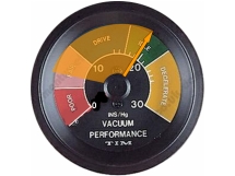 |
| Needle steady between 8 and 14 = Wrong valve timing |
| Needle steady, lower than normal = poor piston rings |
| Needle floats between 12 and 16 = poor carb adjustment |
| Needle steady, below 5 = carb or manifold gasket leak |
| Normal at start - drops quickly = plugged muffler |
| Needle drifts from 14-16 = plug gap too close |
| Needle drifts from 5 to 19 = inter cylinder compression leak |
| Needle drops each time a bad cylinder fires = valve problems |
 |