Happy New Year
14/03/8 3H
What on Earth did we get up to? I had such a horrific day that I can't remember anything at all about it. Oh now I rememember.....
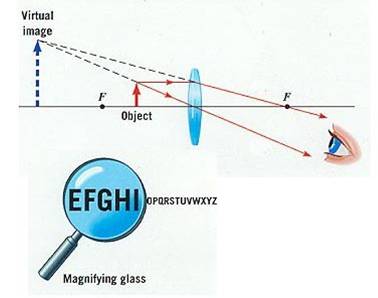
We looked at some really small stuff through convex lenses. They act as magnifying glasses when the object you are looking at is relatively close to the lens.
As the lens is moved further from the object, the image gets bigger, goes blurry and then turns upsidedown.
Look at this, it helps explain what is going on.
Optical bench practical, then a test.
We looked at the use of lenses in forming images.
We did an experiment to see how lenses can be used to form images.
Putting an object close to a convex lens means that it acts like a magnifying glass and forms a virtual image if you look through it.
We also tested putting an object at different distances away from the lens. Real images were then projected onto a screen. The image was either smaller than the object with the object far away (acting like a camera) or it was larger (acting like a slide projector). In both cases the image was upside down.
With the object you were looking at close to the lens, a magnified image is seen through the lens. It is "virtual" (not really there).
If you changed the distance of the object from the lens then the image turned upside down.
This animation shows excellently what was happening.
The eye uses a convex lens to form an image on the retina at the back of the eye, hence allowing you to see!

The eye and a camera both operate in the same basic way. All the rays from the same point on an object are focussed onto the same point on the film/retina by a convex lens.
HW Take your books and sort them out! I need all the HWs on light to be complete and obvious when you hand them in on Monday. These are the prism practical Qs
1. What is the minimum angle of incidence that will achieve Total Internal Reflection (TIR) in Perspex?
2. What 2 lines is the angle of incidence measured between?
3. What are the 3 primary colours?
4. What are the 3 secondary colours?
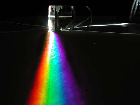
5. Refraction can split white light into a rainbow spectrum. How does it do this?
6. Which colour of light can plants not use to drive photosynthesis?
7. What colour would a red carpet appear under a cyan spotlight?
What on Earth did we get up to? I had such a horrific day that I can't remember anything at all about it. Oh now I rememember.....
We looked at some really small stuff through convex lenses. They act as magnifying glasses when the object you are looking at is relatively close to the lens.
As the lens is moved further from the object, the image gets bigger, goes blurry and then turns upsidedown.
Look at this, it helps explain what is going on.
We went through the test, which was generally OK.
We did some practical work on lenses.
A convex lens converges parallel rays of light to a point. This is called the focal point of the lens, and the distance between the centre of the lens and the focal point is called the focal length.
A concave lens diverges (spreads out) parallel rays. It has a focal point which is imaginary, made by continuing the spreading out rays onwards. Diverging lenses have a negative focal length.

HW Find ray diagrams showing the correction of long and short sight using lenses and copy/cut and paste them into your book.
We learned how to draw ray diagrams for convex lenses - exactly as above! Books in.
Test as promised.
No. RM = CCF. Vision correction posters?
Excessive noise, and noise reduction were discussed. The decibel scale etc.
We then talked about waves in general for a bit and a property they have - diffraction.
Diffraction: Waves spread out when passing through a gap. The smaller the gap, the more spread out the waves become. If the gap is much larger than the wavelength, then diffraction less unnoticeable.
Light is very rarely seen to diffract due to its very small wavelength (between 4 and 7 10 millionths of a metre). In order for noticeable diffraction to occur the wave must pass through a gap which is similar in size to its wavelength. (Note, waves also diffract around obstacles which are similar in size to their wavelength.)
HW Revise for a test on all waves, light and sound so far.
Magnifying glass bits and bobs.
With the object you were looking at close to the lens, a magnified image is seen through the lens. It is "virtual" (not really there).
If you changed the distance of the object from the lens then the image turned upside down.
This animation shows excellently what was happening.
The eye uses a convex lens to form an image on the retina at the back of the eye, hence allowing you to see!
The eye and a camera both operate in the same basic way. All the rays from the same point on an object are focussed onto the same point on the film/retina by a convex lens.
Ultrasound and wavespeed.
Ultrasound is any sound above the range of human hearing (20000Hz). It is useful to use because it has a high frequency and a small wavelength (all sound travels at the same speed). It therefore bounces off small sized objects and can be used to pick up fine details in medical scans etc. Bats and dolphins use it to "see" (active acoustic scanning) and boats and submarines make heavy use of it in sonar.
Other uses include: destroying kidney stones, vasectomies (ouch) and cleaning delicate equipment.
We did a couple of questions on waves. A new formula was introduced.
Wavespeed = Frequency * Wavelength
We need to carry them on next time please....
Prism puzzles and then flat lenses.
You used triangular glass prisms to solve several puzzles using the effects of refraction and total internal reflection.
We did some practical work on lenses.
A convex lens converges parallel rays of light to a point. This is called the focal point of the lens, and the distance between the centre of the lens and the focal point is called the focal length.
A concave lens diverges (spreads out) parallel rays. It has a focal point which is imaginary, made by continuing the spreading out rays onwards. Diverging lenses have a negative focal length.
HW Answer all the questions from both the prism puzzle worksheet and the lenses worksheet.
Bell in a vacuum jar and the speed of sound.
We looked at a bell ringing in a glass jar. The air was sucked out of the jar and we could no longer hear the bell. Sound requires a medium to travel, in a vacuum sound cannot propagate. Light, however, travels easily through a vacuum. This is because it is a wave of oscillating electric and magnetic fields.
Light is an electromagnetic wave. Radiowaves, microwaves, infrared waves (those that carry heat), ultraviolet light, X rays and gamma rays are all also part of the electromagnetic spectrum and can move through a vacuum. They all move at the speed of light, which is 300 million metres a second.
We made a measurement of the speed of sound by bouncing a loud noise made from th top of school off the Tate modern building and timing how long the sound took to get there and back. We used a map to find the distance to the Tate.
Our times were not particularly accurate even though we took an average of 4 readings. Human reaction time may have effected this.
Our speed of sound came out as about 250m/s whereas the true value is more like 330m/s
HW Speed of sound questions 1-5 only.
Computer room work on the optical fibres and analogue and digital mini-project.
HW This must be finished by Wednesday.
More on sound.
We played some sounds into a microphone connected to an oscilloscope. This makes it much easier to see things like amplitude and wavelength. The sound is converted into an electrical signal by the microphone and can then be represented as a transverse wave.
Important quantities that you know are:
1. Amplitude - the maximum "height" of the vibration. Easy to see in a transverse wave, not so easy in a longitudunal.
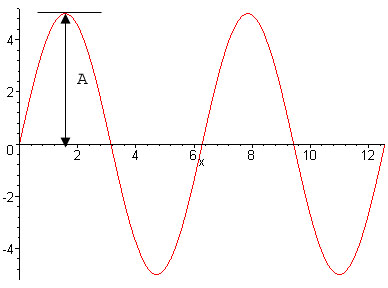
2. Frequency - the number of vibrations a second, measured in Hertz (Hz)
HW Answer all the questions on the worksheet in your book.
We saw a video on optical fibres. Light entering the cable at one end is totally internally reflected all the way to the other end, as long as it doesn't strike the internal suface at less than the critical angle.
Advantages of optical fibres over electrical wires are:
There are a couple of disadvantages: It is hard to join (splice) optical fibres together accurately. Also, the very careful manufacturing process required for optical fibres means they need high technology and expensive factories to make them.
We also discussed the difference between an analogue and a digital signal. Which is entirely seperate to the difference between the comparisons af sending light down an electric cable or an optical fibre.
An analogue signal is an exact copy of a signal (such as a sound wave). A digital signal records the level of the original signal many times a second and so the information can be sent as a series of numbers.
The series of numbers is usually turned into binary code which means it is turned into base 2. The only possible numbers in base 2 are 1 or zero.
It is much easier to retain the quality of a signal if it is sent in binary code. Any interference does not usually stop the ability of the reciever to tell the difference between a 1 or 0.
HW Big mini-project on:
How optical fibres work
The advantages of optical fibres over electrical signals
The difference between digital and analogue signals
The advantage of sending signals digitally. Due in one weeks time (next Wed).
Light is a type of wave. Waves transfer energy from one place to another without transfering matter from one place to another. The energy is transferred as vibrations in a material, called the medium
We saw 2 different types of waves produced on a slinky.
Waves come in 2 major types, transverse and longitudunal.
In transverse waves, vibrations occur which are perpendicular to the direction in which the wave is travelling. e.g. water waves, light.
Longitudunal waves have vibrations which are parallel to the direction of wave travel.
We saw several demonstrations relating to sound.
Sound is a longitudunal wave (as above) where the vibrations in the medium take place in the same direction as the wave is travelling.
We saw how a loudspeaker vibrates in order to cause sound and the vibrations travel through the air.
We also tested the range of frequencies that humans can hear using a signal generator and a loudspeaker. Most of you could hear sound between 20Hz and about 20kHz. I could only hear up to about 14kHz because I am old and rubbish.
Important quantities that you know are:
1. Amplitude - the maximum "height" of the vibration. Easy to see in a transverse wave, not so easy in a longitudunal.
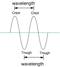
2. Wavelength - The distance from the peak of one wave, to the peak of the next. It can really be measured from any point on the wave, to the next equivalent point.
We looked at the Physics of musical instruments. All sounds are produced by an initial vibration. Musical instruments use reeds (woodwind), lips (brass), strings etc. to start the vibration. The vibration must then be amplified by a sound box or tube. The air inside the tube in a saxophone, for instance, vibrates up and down forced by the reed. This creates a much louder sound which can be made even louder by blowing harder. By changing the length of the column of air (putting keys down), the note can be changed. The larger column of air vibrates at a slower frequency and so plays a lower note.
Remember - sound is a longitudunal wave. In order to see the shape of the wave we transfer it to an electrical signal with a microphone. We can look at the shape of the electrical signal and find out things about the sound. A louder sound has a higher amplitude, a higher pitched sound has a higher frequency and a smaller wavelength.
We made some test tube pan pipes by filling them with various amounts of water. The vibration in them was started in a similar way to a flute.

HW None just yet. It will be set after the single lesson instead.
Total internal reflection (as seen in the semi circular glass block experiment) can be used to carry light down transparent cables, called optical fibres.
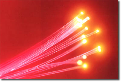
Light enters the cable at one end and leaves at the other. Every time it hits the internal surface of the cable, it strikes at greater than the critical angle. Therefore total internal reflection occurs and it passes on through the cable.

We saw a video on optical fibres. Light entering the cable at one end is totally internally reflected all the way to the other end, as long as it doesn't strike the internal suface at less than the critical angle.
Advantages of optical fibres over electrical wires are:
There are a couple of disadvantages: It is hard to join (splice) optical fibres together accurately. Also, the very careful manufacturing process required for optical fibres means they need high technology and expensive factories to make them.
Pulse code modulation was looked at - how to sample a sound wave, turn it into a digital signal and then recreate the original sound wave.
HW Big mini-project on:
How optical fibres work
The advantages of optical fibres over electrical signals
The difference between digital and analogue signals
The advantage of sending signals digitally.
We did an experiment to see how the angle of a ray of light changed as it exited a glass block.

The ray doesn't bend on the way in, it is at 90 degrees to the glass surface. It turns away from the normal on the way out, as it speeds up. It obeys Snell's law in this case.

As the angle increases, the ray is refracted nearer to the glass surface and is split into a coloured spectrum and a weak reflected ray appears.
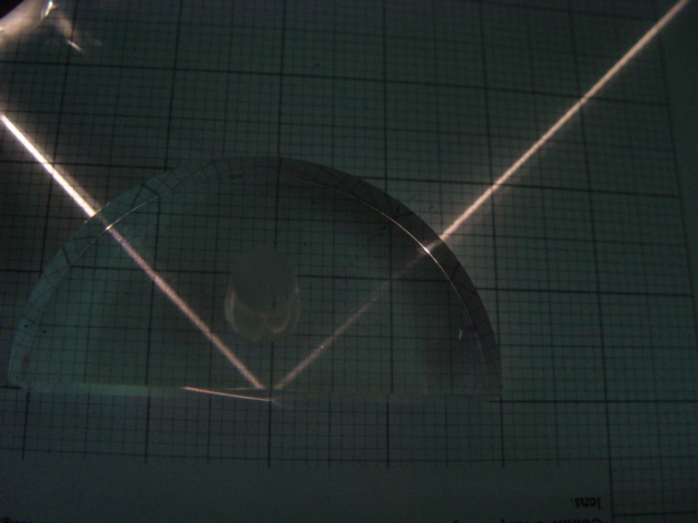
Above a certain angle, the critical angle (about 42 degrees for glass) all of the ray is reflected back. This is called total internal reflection
HW Complete the graph, and answer all the questions on the handout for the practical sheet - if not completed in the lesson.

An endoscope makes use of total internal internal reflection to look inside people.
 HW Finish off - I went to t.tennis with Ping, who won!
More on optical fibres, then analogue and digital signals.
Total internal reflection (as seen in the semi circular glass block experiment) can be used to carry light down transparent cables, called optical fibres.
Light enters the cable at one end and leaves at the other. Every time it hits the internal surface of the cable, it strikes at greater than the critical angle. Therefore total internal reflection occurs and it passes on through the cable.
We saw a video on optical fibres. Light entering the cable at one end is totally internally reflected all the way to the other end, as long as it doesn't strike the internal suface at less than the critical angle.
Advantages of optical fibres over electrical wires are:
There are a couple of disadvantages: It is hard to join (splice) optical fibres together accurately. Also, the very careful manufacturing process required for optical fibres means they need high technology and expensive factories to make them.
We also discussed the difference between an analogue and a digital signal. Which is entirely seperate to the difference between the comparisons af sending light down an electric cable or an optical fibre.
An analogue signal is an exact copy of a signal (such as a sound wave). A digital signal records the level of the original signal many times a second and so the information can be sent as a series of numbers.
The series of numbers is usually turned into binary code which means it is turned into base 2. The only possible numbers in base 2 are 1 or zero.
It is much easier to retain the quality of a signal if it is sent in binary code. Any interference does not usually stop the ability of the reciever to tell the difference between a 1 or 0.
HW Not set yet - it's a slightly bigger than usual one, which I'll set on Tursday instead.
Snell's law calculations were demonstrated.
We saw a video summarising refraction, and then half a video talking about the use of total internal reflection in optical fibres. Much more on this next time.
An experiment was carried out to see how much rays of light bent when they passed into a glass or perspex block. Rays were found to always bend towards the normal line (90 degrees from the glass surface) when they entered the block. This bending is called refraction. It happens because the light changes speed as it enters the perspex block.
There was a mathematical relationship between the angle of incidence (angle between ray on the way in and the normal) and the angle of refraction (angle between the ray inside the block that has changed direction and the normal)
This used the function sin . sin i was proportional to sin r . You will learn about sin in maths.
sin i / sin r (the gradient of the graph you plotted) gave us an idea of how much perspex bent light. This is a property of the perspex known as its refractive index, n. Our answer was about 1.4. This means that light travels 1.4 times slower in perspex than it does in air. (air hardly slows down light at all - it has a refractive index of very slightly over 1)
Your experimental work was taken to be assessed.
HW P89-91 Qs 1-8 in your book.
We did an experiment to see how the angle of a ray of light changed as it exited a glass block.
The ray doesn't bend on the way in, it is at 90 degrees to the glass surface. It turns away from the normal on the way out, as it speeds up. It obeys Snell's law in this case.
As the angle increases, the ray is refracted nearer to the glass surface and is split into a coloured spectrum and a weak reflected ray appears.
Above a certain angle, the critical angle (about 42 degrees for glass) all of the ray is reflected back. This is called total internal reflection
HW Complete the graph, and answer all the questions on the handout for the practical sheet - if not completed in the lesson.
An endoscope makes use of total internal internal reflection to look inside people.
Mohit needs a retest.
Recap on colour mixing questions - big old practical next time, come prepared to do good work.
We looked at some problems involving Snell's law. I concluded that this topic would be better taught after you had done trigonometry in maths.....
We went through the test, mostly OK - some resitters though.
Then we started the new topic - light.
Light is invisible, unless it actually enters your eye.

You can only see the path of the beam when talcum powder or dust reflects some of the light into your eye.
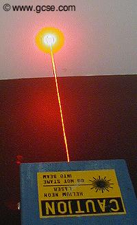
Light always travels in straight lines unless it hits something. The speed of light is 300000000m/s

The angle of incidence always equalled the angle of reflection. Remember that all angles are measured from the normal line.
The effects of curved mirrors.

Mirror images are virtual, and always left to right inverted.
The primary colours are red, green and blue. Mix all three together and we see white. This is due to us having seperate red, green and blue colour sensitive cones in our retinas. When they all fire off simultaneously, we see white.
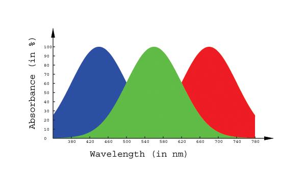

However, white light from the Sun comes with all of the the colours of the rainbow present (RedOrangeYellowGreenBlueIndigoViolet). Light can be split into its constituent parts by using a prism, this also occurs naturally in a rainbow.
Red objects appear red because they absorb all light except red, which they reflect. Shine green light on a red object and it will look black. A red filter only allows red light ot pass through it. A blue filter only allows blue light to pass through it. Put a red filter in front of a blue one and no light at all can get through.
Light always travels in straight lines unless it hits something.
We can use this principal to make a pinhole camera.
Light travels into a box only through a pinhole and shines on an opposite screen. An upside down image of the object you are looking at therefore forms on the screen.
We did a little practical on refraction.
Some coins had been stuck into the bottom of some metal beakers. The coins, which were slightly out of view, became visible when the metal beakers were filled with water. This could not be explained by light travelling in straight lines. The light that reflected from the coin was bent somehow when it moved from the water back out into the air. This allowed us to see "around the corner".
This phenomenon is known as refraction. It occurs because light travels at a slower speed in transparent mediums (materials that it can pass through)than it does in air/a vacuum.

This also makes objects viewed underwater appear shallower than they actually are.
We looked some more at the phenomenon of refraction.
We did an apparent depth practical. By lining up pins, we could work out the apparent position of a pin when viewed through a perspex block. This meant intersecting 2 different rays.

The refractive index of a transparent material can be found by dividing the actual depth by the apparent depth of an object viewed through it.
The refractive index is a measure of how much light is slowed down by the material.
Speed of light in a material = Speed of light in a vacuum / Refractive index
An experiment was carried out to see how much rays of light bent when they passed into a glass or perspex block. Rays were found to always bend towards the normal line (90 degrees from the glass surface) when they entered the block. This bending is called refraction. It happens because the light changes speed as it enters the perspex block.
There was a mathematical relationship between the angle of incidence (angle between ray on the way in and the normal) and the angle of refraction (angle between the ray inside the block that has changed direction and the normal)
This used the function sin . sin i was proportional to sin r . You will learn about sin in maths.
sin i / sin r (the gradient of the graph you plotted) gave us an idea of how much perspex bent light. This is a property of the perspex known as its refractive index, n. Our answer was about 1.4. This means that light travels 1.4 times slower in perspex than it does in air. (air hardly slows down light at all - it has a refractive index of very slightly over 1)
Your experimental work was taken to be assessed.
HW Question sheet on Snell's law. Don't worry too much about the 2nd half of the 2nd side....
Electricity test as promised.
We loked some more at the phenomenon of refraction.
We did an apparent depth practical. By lining up pins, we could work out the apparent position of a pin when viewed through a perspex block. This meant intersecting 2 different rays.
The refractive index of a transparent material can be found by dividing the actual depth by the apparent depth of an object viewed through it.
The refractive index is a measure of how much light is slowed down by the material.
Speed of light in a material = Speed of light in a vacuum / Refractive index
As promised, revision of electricity.
HW Revise for a test on electricity next time.
We went through the test, mostly OK - some resitters though.
Then we started the new topic - light.
Light is invisible, unless it actually enters your eye.
You can only see the path of the beam when talcum powder or dust reflects some of the light into your eye.
Light always travels in straight lines unless it hits something. The speed of light is 300000000m/s
The angle of incidence always equalled the angle of reflection. Remember that all angles are measured from the normal line.
The effects of curved mirrors.
Mirror images are virtual, and always left to right inverted.
The primary colours are red, green and blue. Mix all three together and we see white. This is due to us having seperate red, green and blue colour sensitive cones in our retinas. When they all fire off simultaneously, we see white.
However, white light from the Sun comes with all of the the colours of the rainbow present (RedOrangeYellowGreenBlueIndigoViolet). Light can be split into its constituent parts by using a prism, this also occurs naturally in a rainbow.
Red objects appear red because they absorb all light except red, which they reflect. Shine green light on a red object and it will look black. A red filter only allows red light ot pass through it. A blue filter only allows blue light to pass through it. Put a red filter in front of a blue one and no light at all can get through.
Light always travels in straight lines unless it hits something.
We can use this principal to make a pinhole camera.
Light travels into a box only through a pinhole and shines on an opposite screen. An upside down image of the object you are looking at therefore forms on the screen.
We did a little practical on refraction.
Some coins had been stuck into the bottom of some metal beakers. The coins, which were slightly out of view, became visible when the metal beakers were filled with water. This could not be explained by light travelling in straight lines. The light that reflected from the coin was bent somehow when it moved from the water back out into the air. This allowed us to see "around the corner".
This phenomenon is known as refraction. It occurs because light travels at a slower speed in transparent mediums (materials that it can pass through)than it does in air/a vacuum.
This also makes objects viewed underwater appear shallower than they actually are.
HW Make sure you have filled in all the responses to the penny in a bucket practical.
We sat the electricity test as promised. It was a bit too long, so I might reduce the "out of" mark.
The resistance of short/long and thin/fat wires.
The longer the wire, the greater it's resistance (more material for the electrons to "scrape" past).
The fatter the wire, the lower the resistance (more room for electrons to flow through.)
Resistors in series and parallel.
Resistors in Series
Simply add them up!
R1 + R2 = RTotal
Resistors in parallel
1/R1 + 1/R2 = 1/Rtotal
This is a little harder, as you have to be able to do some maths. Here is an example:
A 3 Ohm resistor is put in parallel with a 12 Ohm resistor, what is the total resitance?
1/R1 + 1/R2 = 1/Rtotal
So 1/3 + 1/12 = 1/Rtotal
1/3 = 4/12
4/12 + 1/12 = 1/Rtotal
= 5/12
Cross multiplying gives: Rtotal = 12/5 = 2.4 Ohms
Your answer will always be somewhat smaller than either of the 2 resistances in parallel.
HW Complete the set of calculations on resistors in series and parallel.
The resistance of short/long and thin/fat wires.
The longer the wire, the greater it's resistance (more material for the electrons to "scrape" past).
The fatter the wire, the lower the resistance (more room for electrons to flow through.)
Resistors in series and parallel.
Resistors in Series
Simply add them up!
R1 + R2 = RTotal
Resistors in parallel
1/R1 + 1/R2 = 1/Rtotal
This is a little harder, as you have to be able to do some maths. Here is an example:
A 3 Ohm resistor is put in parallel with a 12 Ohm resistor, what is the total resitance?
1/R1 + 1/R2 = 1/Rtotal
So 1/3 + 1/12 = 1/Rtotal
1/3 = 4/12
4/12 + 1/12 = 1/Rtotal
= 5/12
Cross multiplying gives: Rtotal = 12/5 = 2.4 Ohms
Your answer will always be somewhat smaller than either of the 2 resistances in parallel.
Potential dividers
We then just began to look at potential dividers. They are simply series circuits which split up the battery voltage between components.
The "output voltage" above depends upon the resistance of the 2 resistors. You could work out the voltage across each resistor using Ohm's law.
Firstly calculate the current in the entire circuit:
I = V / RT
Where RT = R1 + R2
(because the 2 resistors are in series you add them together to find the total resistance of the circuit.)
The current is the same through both resistors because they are in series. You can calculate the voltage across them using Ohm's law again. (V = IR)
VR1 = I R1
(and the same for R2)
However, there is a shortcut formula which sidesteps calculating the current. You simply know that each resistor takes the same proportion of the total voltage as its proportion of the total resistance of the circuit.
Algebraically, this looks a bit like this:
A potential divider circuit can be used to provide the input voltage to a transistor (an electronic "switch"). This is particularly useful if the potential divider contains a component like a thermistor. As the external temperature increases, the resistance of the thermistor falls, and the voltage across the thermistor gets smaller. A transistor can be used to switch on a warning light when the temperature gets too high/low.
![]()
The above circuit turns on the lamp when light levels hitting the LDR get higher.
HW Revise for an electricity test