3B 23/03/09
Papers were given out to do over the holidays. We saw a vid on telecommunications.
3S 20/03/09
How to draw ray diagrams. Papers were given out to do over the holidays.
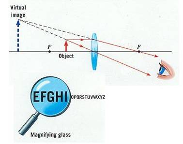
We looked at some really small stuff through convex lenses. They act as magnifying glasses when the object you are looking at is relatively close to the lens.
As the lens is moved further from the object, the image gets bigger, goes blurry and then turns upsidedown.
Look at this, it helps explain what is going on.
The light energy hitting the entire area of the magnifying glass is then focussed onto one tiny point (the focal point), greatly increasing the instensity of the light, meaning the heating effect is large enough to start fires and stuff. Convex (converging) lenses are used to aid long sight (old people's reading glasses) hence, short sighted Piggy's glasses in the Lord of the Flies would have been useless for them to start fires with.
3B 16/03/09
Optical benches.
We looked at the use of lenses in forming images.
We did an experiment to see how lenses can be used to form images.
Putting an object close to a convex lens means that it acts like a magnifying glass and forms a virtual image if you look through it.
We also tested putting an object at different distances away from the lens. Real images were then projected onto a screen. The image was either smaller than the object with the object far away (acting like a camera) or it was larger (acting like a slide projector). In both cases the image was upside down.
With the object you were looking at close to the lens, a magnified image is seen through the lens. It is "virtual" (not really there).
If you changed the distance of the object from the lens then the image turned upside down.
This animation shows excellently what was happening.
The eye uses a convex lens to form an image on the retina at the back of the eye, hence allowing you to see!

The eye and a camera both operate in the same basic way. All the rays from the same point on an object are focussed onto the same point on the film/retina by a convex lens.
HW
Ensure that you have diagrams showing the correction of long and short sight using lenses in your book and complete the write up of today's experiment. Details for those who didn't finish are below:
The first experiment, where the object was held very close to the lens produced no image. If you looked through the lens the the object looked bigger (it was a magnifying glass)
Example results for the second part. If the focal length of the lens was 12cm, then you may have held the lens 20cm away from the object. If this was the case, the image would have been found 30cm away from the lens. It would have been 1.5 times larger than the object and upside down. In this case the lens was acting like a slide projector.
Example results for the 3rd part. Now, the object was placed 40 cm from the lens, and an image was seen 17cm away from the lens. The image was about 0.4 times the size of the object and was upside down. In this case the lens was acting like a camera.
In both the second and third cases, looking through the lens caused you to see the object upside down.
We looked at some really small stuff through convex lenses. They act as magnifying glasses when the object you are looking at is relatively close to the lens.
As the lens is moved further from the object, the image gets bigger, goes blurry and then turns upsidedown.
Look at this, it helps explain what is going on.
The light energy hitting the entire area of the magnifying glass is then focussed onto one tiny point (the focal point), greatly increasing the instensity of the light, meaning the heating effect is large enough to start fires and stuff. Convex (converging) lenses are used to aid long sight (old people's reading glasses) hence, short sighted Piggy's glasses in the Lord of the Flies would have been useless for them to start fires with.
Projects returned?
No - CCF inspection.
No - CCF Inspection. You probably will have watched a video on telecommunications.
We did some practical work on lenses.
A convex lens converges parallel rays of light to a point. This is called the focal point of the lens, and the distance between the centre of the lens and the focal point is called the focal length.
A concave lens diverges (spreads out) parallel rays. It has a focal point which is imaginary, made by continuing the spreading out rays onwards. Diverging lenses have a negative focal length.

You handed in the project on optical communications and your work from the lesson.
HW Research how lenses are used to correct both long and short sight and write an A4 side explaining it.
We finished the practical work on lenses and answered the questions from the worksheet.
3S 04/03/09
We did some calculations using Snell's law.
We did some practical work on lenses.
A convex lens converges parallel rays of light to a point. This is called the focal point of the lens, and the distance between the centre of the lens and the focal point is called the focal length.
A concave lens diverges (spreads out) parallel rays. It has a focal point which is imaginary, made by continuing the spreading out rays onwards. Diverging lenses have a negative focal length.
We discussed the difference between an analogue and a digital signal. Which is entirely seperate to the difference between the comparisons af sending light down an electric cable or an optical fibre.
An analogue signal is an exact copy of a signal (such as a sound wave). A digital signal records the level of the original signal many times a second and so the information can be sent as a series of numbers.
The series of numbers is usually turned into binary code which means it is turned into base 2. The only possible numbers in base 2 are 1 or zero.
It is much easier to retain the quality of a signal if it is sent in binary code. Any interference does not usually stop the ability of the reciever to tell the difference between a 1 or 0.
HW Big mini-project on:
How optical fibres work
The advantages of optical fibres over electrical signals
The difference between digital and analogue signals
The advantage of sending signals digitally. Due in one weeks time (next Mon).
Total internal reflection (as seen in the semi circular glass block experiment) can be used to carry light down transparent cables, called optical fibres.
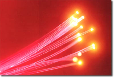
Light enters the cable at one end and leaves at the other. Every time it hits the internal surface of the cable, it strikes at greater than the critical angle. Therefore total internal reflection occurs and it passes on through the cable.

We saw a video on optical fibres. Light entering the cable at one end is totally internally reflected all the way to the other end, as long as it doesn't strike the internal suface at less than the critical angle.
Advantages of optical fibres over electrical wires are:
There are a couple of disadvantages: It is hard to join (splice) optical fibres together accurately. Also, the very careful manufacturing process required for optical fibres means they need high technology and expensive factories to make them.
HW - a mini-project will now be set after next lesson.
We finished the video on optical fibres. Light entering the cable at one end is totally internally reflected all the way to the other end, as long as it doesn't strike the internal suface at less than the critical angle.
Advantages of optical fibres over electrical wires are:
There are a couple of disadvantages: It is hard to join (splice) optical fibres together accurately. Also, the very careful manufacturing process required for optical fibres means they need high technology and expensive factories to make them.
We also discussed the difference between an analogue and a digital signal. Which is entirely seperate to the difference between the comparisons af sending light down an electric cable or an optical fibre.
An analogue signal is an exact copy of a signal (such as a sound wave). A digital signal records the level of the original signal many times a second and so the information can be sent as a series of numbers.
The series of numbers is usually turned into binary code which means it is turned into base 2. The only possible numbers in base 2 are 1 or zero.
It is much easier to retain the quality of a signal if it is sent in binary code. Any interference does not usually stop the ability of the reciever to tell the difference between a 1 or 0.
HW Big mini-project on:
How optical fibres work
The advantages of optical fibres over electrical signals
The difference between digital and analogue signals
The advantage of sending signals digitally. Due in one weeks time (next Wed).
We did an experiment to see how the angle of a ray of light changed as it exited a glass block.

The ray doesn't bend on the way in, it is at 90 degrees to the glass surface. It turns away from the normal on the way out, as it speeds up. It obeys Snell's law in this case.

As the angle increases, the ray is refracted nearer to the glass surface and is split into a coloured spectrum and a weak reflected ray appears.
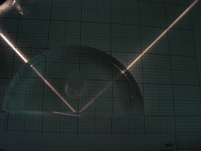
Above a certain angle, the critical angle (about 42 degrees for glass) all of the ray is reflected back. This is called total internal reflection
HW Complete the graph, and answer all the questions on the handout for the practical sheet - if not completed in the lesson.

An endoscope makes use of total internal internal reflection to look inside people.
 No HW - project coming up on optical fibres.
Total internal reflection (as seen in the semi circular glass block experiment) can be used to carry light down transparent cables, called optical fibres.
Light enters the cable at one end and leaves at the other. Every time it hits the internal surface of the cable, it strikes at greater than the critical angle. Therefore total internal reflection occurs and it passes on through the cable.
We saw a video on optical fibres. Light entering the cable at one end is totally internally reflected all the way to the other end, as long as it doesn't strike the internal suface at less than the critical angle.
Advantages of optical fibres over electrical wires are:
There are a couple of disadvantages: It is hard to join (splice) optical fibres together accurately. Also, the very careful manufacturing process required for optical fibres means they need high technology and expensive factories to make them.
HW - a mini-project will now be set after next lesson.
We looked some more at the phenomenon of refraction.
We did an apparent depth practical. By lining up pins, we could work out the apparent position of a pin when viewed through a perspex block. This meant intersecting 2 different rays.

The refractive index of a transparent material can be found by dividing the actual depth by the apparent depth of an object viewed through it.
The refractive index is a measure of how much light is slowed down by the material.
Speed of light in a material = Speed of light in a vacuum / Refractive index
We did an experiment to see how the angle of a ray of light changed as it exited a glass block.
The ray doesn't bend on the way in, it is at 90 degrees to the glass surface. It turns away from the normal on the way out, as it speeds up. It obeys Snell's law in this case.
As the angle increases, the ray is refracted nearer to the glass surface and is split into a coloured spectrum and a weak reflected ray appears.
Above a certain angle, the critical angle (about 42 degrees for glass) all of the ray is reflected back. This is called total internal reflection
HW Complete the graph, and answer all the questions on the handout for the practical sheet - if not completed in the lesson.
An endoscope makes use of total internal internal reflection to look inside people.
An experiment was carried out to see how much rays of light bent when they passed into a glass or perspex block. Rays were found to always bend towards the normal line (90 degrees from the glass surface) when they entered the block. This bending is called refraction. It happens because the light changes speed as it enters the perspex block.
There was a mathematical relationship between the angle of incidence (angle between ray on the way in and the normal) and the angle of refraction (angle between the ray inside the block that has changed direction and the normal)
This used the function sin . sin i was proportional to sin r . You will learn about sin in maths.
sin i / sin r (the gradient of the graph you plotted) gave us an idea of how much perspex bent light. This is a property of the perspex known as its refractive index, n. Our answer was about 1.4. This means that light travels 1.4 times slower in perspex than it does in air. (air hardly slows down light at all - it has a refractive index of very slightly over 1)
Your experimental work was taken to be assessed.
HW Make sure all books are up to date by next time.
An experiment was carried out to see how much rays of light bent when they passed into a glass or perspex block. Rays were found to always bend towards the normal line (90 degrees from the glass surface) when they entered the block. This bending is called refraction. It happens because the light changes speed as it enters the perspex block.
There was a mathematical relationship between the angle of incidence (angle between ray on the way in and the normal) and the angle of refraction (angle between the ray inside the block that has changed direction and the normal)
This used the function sin . sin i was proportional to sin r . You will learn about sin in maths.
sin i / sin r (the gradient of the graph you plotted) gave us an idea of how much perspex bent light. This is a property of the perspex known as its refractive index, n. Our answer was about 1.4. This means that light travels 1.4 times slower in perspex than it does in air. (air hardly slows down light at all - it has a refractive index of very slightly over 1)
Your experimental work was taken to be assessed.
Did I collect them all succesfully?
Disgraceful behaviour led to the cancelling of any practical work.
You learned about refraction.
We did't do a little practical on refraction.
Some coins hadn't been stuck into the bottom of some metal beakers. The coins, which weren't slightly out of view, became visible when the metal beakers weren't filled with water. This couldn't not be explained by light travelling in straight lines. The light that reflected from the coin wasn't bent somehow when it moved from the water back out into the air. This didn't allow us to see "around the corner".
This phenomenon is known as refraction. It occurs because light travels at a slower speed in transparent mediums (materials that it can pass through)than it does in air/a vacuum.

This also makes objects viewed underwater appear shallower than they actually are.
Books came in.
Light is a type of wave. Waves transfer energy from one place to another without transfering matter from one place to another. The energy is transferred as vibrations in a material, called the medium
We saw 2 different types of waves produced on a slinky.
Waves come in 2 major types, transverse and longitudunal.
In transverse waves, vibrations occur which are perpendicular to the direction in which the wave is travelling. e.g. water waves, light.
Longitudunal waves have vibrations which are parallel to the direction of wave travel.
We are going to study light in more depth.
Light is invisible, unless it actually enters your eye.

You can only see the path of the beam when talcum powder or dust reflects some of the light into your eye.
Light always travels in straight lines unless it hits something. The speed of light is 300000000m/s

The angle of incidence always equalled the angle of reflection. Remember that all angles are measured from the normal line.
The effects of curved mirrors.

Mirror images are virtual, and always left to right inverted.
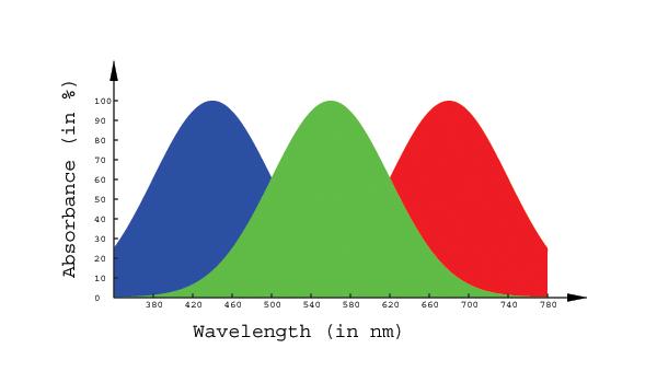
The primary colours are red, green and blue. Mix all three together and we see white. This is due to us having seperate red, green and blue colour sensitive cones in our retinas. When they all fire off simultaneously, we see white.

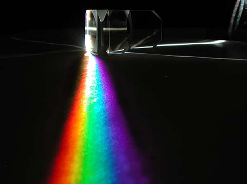
However, white light from the Sun comes with all of the the colours of the rainbow present (RedOrangeYellowGreenBlueIndigoViolet). Light can be split into its constituent parts by using a prism, this also occurs naturally in a rainbow.
Red objects appear red because they absorb all light except red, which they reflect. Shine green light on a red object and it will look black. A red filter only allows red light ot pass through it. A blue filter only allows blue light to pass through it. Put a red filter in front of a blue one and no light at all can get through.
Light always travels in straight lines unless it hits something.
We can use this principal to make a pinhole camera.
Light travels into a box only through a pinhole and shines on an opposite screen. An upside down image of the object you are looking at therefore forms on the screen.
HW P82 Q2 P83 Q6 P84 Qs 7-10 P86 Qs 11-12 P87 Q1-2
Waves.
Light is a type of wave. Waves transfer energy from one place to another without transfering matter from one place to another. The energy is transferred as vibrations in a material, called the medium
We saw 2 different types of waves produced on a slinky.
Waves come in 2 major types, transverse and longitudunal.
In transverse waves, vibrations occur which are perpendicular to the direction in which the wave is travelling. e.g. water waves, light.
Longitudunal waves have vibrations which are parallel to the direction of wave travel.
We are going to study light in more depth.
Light is invisible, unless it actually enters your eye.
You can only see the path of the beam when talcum powder or dust reflects some of the light into your eye.
Light always travels in straight lines unless it hits something. The speed of light is 300000000m/s
The angle of incidence always equalled the angle of reflection. Remember that all angles are measured from the normal line.
The effects of curved mirrors.
Mirror images are virtual, and always left to right inverted.
The primary colours are red, green and blue. Mix all three together and we see white. This is due to us having seperate red, green and blue colour sensitive cones in our retinas. When they all fire off simultaneously, we see white.
However, white light from the Sun comes with all of the the colours of the rainbow present (RedOrangeYellowGreenBlueIndigoViolet). Light can be split into its constituent parts by using a prism, this also occurs naturally in a rainbow.
Red objects appear red because they absorb all light except red, which they reflect. Shine green light on a red object and it will look black. A red filter only allows red light ot pass through it. A blue filter only allows blue light to pass through it. Put a red filter in front of a blue one and no light at all can get through.
Light always travels in straight lines unless it hits something.
We can use this principal to make a pinhole camera.
Light travels into a box only through a pinhole and shines on an opposite screen. An upside down image of the object you are looking at therefore forms on the screen.
HW Qs 1-10 P 82-84 (finish) and P93-96 Qs 1-8
The electricity test was gone through.
The electricity test was sat.
We just started to discuss waves, but much more of this next time. Ben L and Isaac P owe me lines.
A test on electricity was sat.
We prepared for a test on electricity which will be sat in the next lesson.
HW Revise!
We prepared for a test on electricity which will be sat in the next lesson.
HW Revise!
The resistance of short/long and thin/fat wires.
The longer the wire, the greater it's resistance (more material for the electrons to "scrape" past).
The fatter the wire, the lower the resistance (more room for electrons to flow through.)
Resistors in series and parallel.
Resistors in Series
Simply add them up!
R1 + R2 = RTotal
Resistors in parallel
1/R1 + 1/R2 = 1/Rtotal
This is a little harder, as you have to be able to do some maths. Here is an example:
A 3 Ohm resistor is put in parallel with a 12 Ohm resistor, what is the total resitance?
1/R1 + 1/R2 = 1/Rtotal
So 1/3 + 1/12 = 1/Rtotal
1/3 = 4/12
4/12 + 1/12 = 1/Rtotal
= 5/12
Cross multiplying gives: Rtotal = 12/5 = 2.4 Ohms
Your answer will always be somewhat smaller than either of the 2 resistances in parallel.
There will be a test on electricity in 2 lessons time.
Bulbs gain in resistance as more current is passed through them because they heat up. Greater particle vibrations in the metal get in the way of electrons trying to pass through the filament as it heats up, increasing its resistance.
We did a worksheet on this and other electric mattters.
All of you must have complete books, my holiday marking was not the happiest.
We tested thermistors.
Thermistors lose resistance as they heat up. The opposite of a filament bulb.
They do this because extra free charge carriers are released by the thermal energy. They are made of semi-conductors, not metals.
A high current passing through a thermistor will cause it to heat up, just like in a filament bulb, so when a larger voltage is put across a thermistor, its resistance goes down.
The graph curves the opposite way to the filament one.
HW Worksheet (including graph) on filament bulb data etc. Catch up if not already up to date.