| Back to Main page | Last updated: Nov 01, 2005 | |||||||||||||||||||||||||||||||||||||||||||||||||||||||||||||||||||||||||||||||||||||||||||||||||||||||||||||||||||||||||||||||||||||||||||||||||||||||||||||||||||||||||||||||||||||||||||||||||||||||||||||||||||||||||||||||||||||||||||
PVC-ROV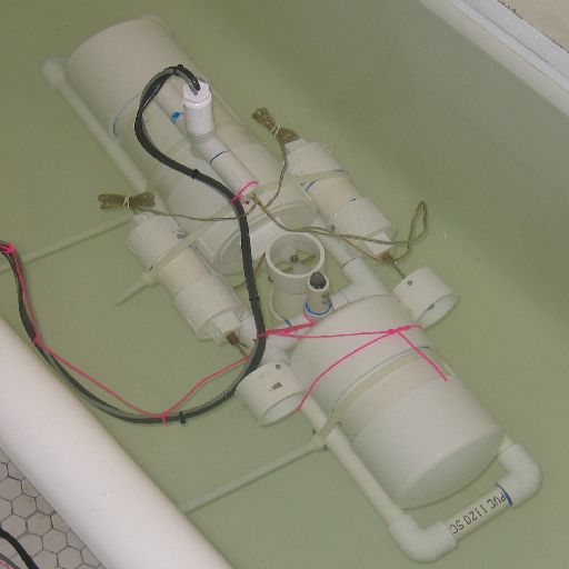
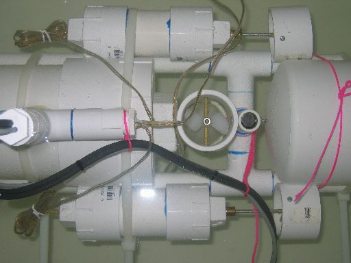
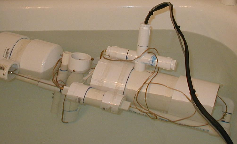
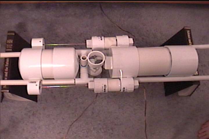
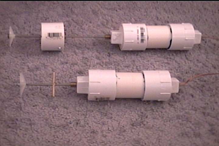
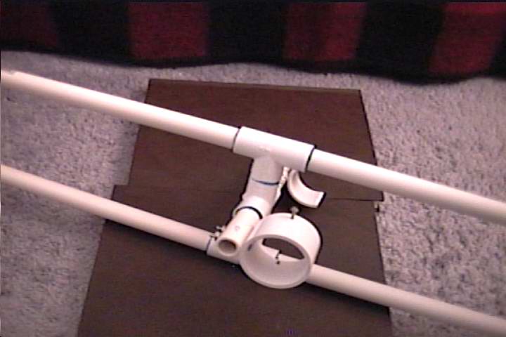
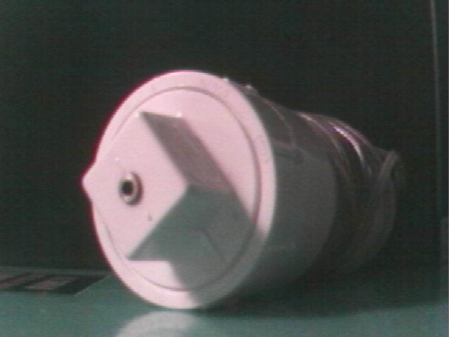
Bathtub test (October 23, 2005) This is a floatation test (12/17/03) - plenty of boyancy. As you can see everything is scotch-taped. There have been some changes in the design deviating from what I said below: Misc thaughts: The ROV will consist of 3 thrusters - 1(up/down) & 2(forward/reverse/turn), hull (front), float (back), and a simple frame. Take a look at all these pictures for more info. Keep in mind that for now side thrusters are scotchtaped and will be attached by cableties. At this time the frame of the ROV is not cut to size - that will allow for a more flexible configuration during floatation trials - for example I might want to move the float back to shift the center of gravity forward. The idea was to make the rov as mechanically simple as possible. The only tool required to build it is an electric drill. I also used Dremel Tool with a drill press attachment to route the Lexan Sheets but that could be done with a small hand saw and files. Electronics on the other hand will be a bit more advanced - I will not use relays or direct drive teather, but will use H-bridges for gradual motor control and RS485 to communicate with a PIC16C84 microcontroller on board. Thrusters are oil filled. Here is how they look inside. I did NOT test the thrusters fully yet and just from a few brief tests I have to admit there are 2 problems:
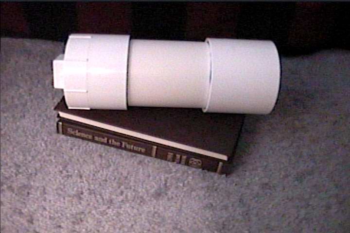
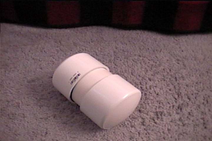
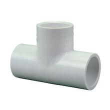
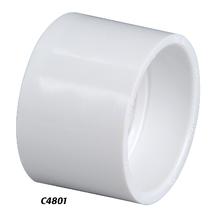
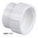
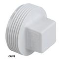
In my previous failed designs I used a motor of about the same size which would drain only 2 amps at near stall current. These are the specs for the motors I use now: Jameco #190035, Mfg Ref # JOHNSONHC685L (Johnson Electric) Voltage Range: 7.2V - 24V (Nominal Voltage: 15VDC) Current: 0.72 Amps, RPM: 7800 max. @15V, Torque: 23.2 g-cm Shaft Diameter: 0.13" ( I had to file it a bit to 0.125") Shaft Length: 0.38", Size: 1.47"D x 2.25"L You can see how one has to be careful - even though their idle current is only 0.72amps ( more like 1.5 amps when I measured it ) the current drained by the thruster in the water is about 17 Amps and out of the water about 10 due to the oil in the thruster and friction with the seal. Since I have a 100 foot 12 gage multistranded ambilical, only about 5 Amps are consumed with ambilical out of the water - that's a large power loss due to resistance in ambilical!!! All the parts for the thrusters I use are posted in the table. See manufacturer's sites to see how individual components look. Thruster housing is made out of 1-1/2" PVC pipe and fittings. Use of the cleanout adapters and plugs makes the design very modular and easy to repair/replace oil. Here is a cross section diagram of the thruster. The hardest parts of the thruster to make are the rings that hold the motor inside the pvc pipe. When making the rings, make sure they fit in the pipe a bit loose since gluing the cleanout adapters will squeeze the pipe and decrease it's diameter ( the way I think it happens is that pvc cement makes the pipe more flexible ) Motor mounting rings are made out of thin clear plastic (although you can make it out of plastic that you use for the viewport) and attached to the motor through holes using small bolts in the front and screws in the back to the plastic part of the motor. I made them by using a tool that makes holes in the sheetrock. After cutting the circles, I put them on a long bolt, fix it with a nut, put the bolt in the drill and ground it down to the needed diameter (inner diameter of the 1-1/2" pvc pipe) by spinning the disk on the file. Then I drill holes for mounting screws in both rings plus motor leads in the back rings only. The only additional work neede is to drill 2 holes in the PVC plugs to mount the seal and let the cable through. Epoxy is used to seal the hole around the cable - I poured about 1/2 inch inside the square part of the plug and used it around and under the seal. Also you need to make a brass pipe sleave that will prevent the shaft from moving in and out of the thruster and shaft coupling from falling out of the seats. I had to use about 1/2 inch pieces of the stuffing box pipe that came with the shaft in my thrusters. When assembling the thruster, put 5 turns of teflon tape on threads of the plug. If you put less than 4, the oil will leak through the threads. I have been trying to build this rov since year 2000. There were 3 failed thurster designs already. These are the pictures of the first failed design. The problem was that I used a brass shaft and a brass seal. I realized that it was a problem only after 2nd design failed. In the 3rd design I used a steel shaft, brass shaft seal, brass couplers and a lot of pvc pieces (the duct was incorporated into the truster). The duct was the fail point since it was held by 3 screwes and the nuts were glued using 5 minute epoxy which broke off. Hull and Float are made out of 4" PVC pipe. If I were to do it over I would probably use 3" PVC not 4" since 4" provides a lot of extra boyancy and lowers the pressure it can withstand to 220 PSI. Float consists of just 6" piece of PVC with endcaps where as Hull is an 8" piece with coupling on one side and a drain adapter on the other. Coupling has a circle of thick Lexan sandwiched between 2 1/2 inch rings of 4" pvc pipe glued in with epoxy and rings held by pvc glue. Also come to think of it, putting the camera and the light in small 1.5" external enclosures with lexan glass ports would probably be better, although more work. Frame is made out of 1/2 inch PVC pipe and fittings and will support Hull/Float and the thrusters. Vertical thruster is mounted into a 1-1/2" coupling which is bolted to the frame. Vertical thruster duct is also bolted to the frame. ROV will have slightly positive boyancy. During tests, just the front Hull was able to support the weight of 2 thruster and displace additional 2-3 lbs of water. Back float can probably provide flotation to 2-3lb of equipment also. Ballast will be made out of led-filled 1/2"OD copper pipes (don't know where to get them yet but I heard they are used for refrigeration) and will fit inside the 1/2 inch frame. This configuration allows to ajust center of gravity and position it directly below vertical thruster. Additional weights can be put into the hull if needed. Howerver it looks like it might be easier just to make lead cylinders that will fit into 1/2" pvc pipe. Depth rating - The weakest component in the ROV is 4" PVC pipe rated to 220 PSI without failsafe zone that would give it a 500 ft depth rating. Another limiting factor is that I am planning to deliver 12V throught the ambilical and therefore think that about 150-300 feet of wire will do. Since I use 7.2V - 24V (15V) motors, I might use 18V or 24V supply - that will take care of the voltage drop accross ambilical and decrease energy dissipation. Ambilical is also a factor - I'm hoping that pvc jacket of a multiconductor wire will hold the pressure. In practice, I have a 100ft ambilical composed of a low voltage 12 gage garden lighting wire and a 4 conductor PVC jacket security cable bundled together by zip ties. Don't know if I will ever get to painting this puppy but it might eventually happen. My dream: to attach a speargun an a laser sight to the ROV and go fishing :) Here is the PIC microcontroller source code for the receiver I am using. It takes TTL serial @ 300 baud (no need to go higher) and converts it to PWM and direction for 6 channels. You can use this PC based program to communicate to the PIC. This program transmitts joystick position to the other side. PC side should use a RS232 to RS485 converter since all communications are over RS485. I was in a process of debugging the transmitter code for a console that would operate without a need for PC but I do not think I will continue working on it since a laptop is the best way to control the ROV and view the video feed. Once the ROV is operation I might put in a digital compas. This will be easy to do due to the nature of RS485 and transmission protocol design(when upper 3 bits are set, data is not used by receiver). Leak detection sensor is a good thing to add to the list also. The camera will remain stationary since I don't have a dome but just a flat viewport. It would be cool to get my hands on a dome but baking lexan in the oven to make one is complicated. I am sure you want to know how much it would cost. So here are approximate prices for components I used:
Plus the bill from DIGI-KEY for electronic parts needed to make H-bridges:
Picture of the electronics This is a pictures of a RS485/PIC board + 3 H-bridges with supporting circuitry. A big thanks to Bevin L. (Subz NZ rov) for advising me to use RS485, Mike N for sharing the information and to all of my friends who are sick of hearing about my ROV by now and want to see it work. If you are serious about building an ROV you should visit this place: Yahoo Robotics & ROV Group. I would really like your feedback regarding this project. E-mail me to rand3289(at)yahoo.com with all your questions and suggestions. All information about this project is accessible to public but can NOT be used for commercial purposes! | ||||||||||||||||||||||||||||||||||||||||||||||||||||||||||||||||||||||||||||||||||||||||||||||||||||||||||||||||||||||||||||||||||||||||||||||||||||||||||||||||||||||||||||||||||||||||||||||||||||||||||||||||||||||||||||||||||||||||||||