![[MWA Engineering Dept.]](circuitheader.gif)
![[MWA Engineering Dept.]](circuitheader.gif)
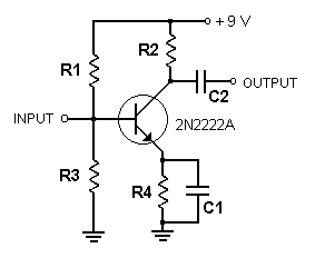
A buffer amp can be inserted between the oscillator and the rest of a transmitter circuit. The buffer not only increases the power of the signal but also prevents the oscillator frequency from being affected by modulation, changes in antenna loading, etc.

Above is the simplest buffer amp we could dig up. It is designed to work with a 9 volt power supply.
Parts:
C1: .1 uF
C2: .01 uF
R1: 27 K
R2: 22 ohms
R3: 5600
R4: 270

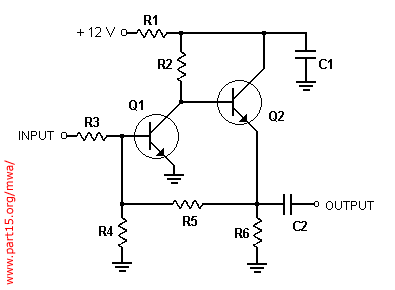
Above is a deluxe buffer amp that uses a pair of bipolar transistors. Some of the resistor values are a little different depending on whether it is built with 3904's or 2222's.
Parts:
| Q1, Q2 | 2N2222A | 2N3904 |
| R1 | 100 | 47 |
| R2 | 1 K | 1 K |
| R3 | 10 K | 10 K |
| R4 | 2200 | 10 K |
| R5 | 10 K | 22 K |
| R6 | 330 | 330 |
| C1 | .1 uF | .1 uF |
| C2 | .01 uF | .01 uF |
![]()
return to transmitter building blocks page or Engineering Dept.
This page copyright 2003 by Medium Wave Alliance. All rights reserved.