Putting it together   


  The transformer has two metal tabs on the bottom. These can be bent out flat, so the transformer can be glued to the printed circuit board, or two holes can be drilled in the board, and the tabs can fit into the holes and be folded over to hold the transformer in place. If you choose to drill the holes and fold over the tabs, the tabs can be soldered to the copper pads on the back of the printed circuit board for a more secure anchor.   


  The transformer should be placed on the left side of the printed circuit board, leaving plenty of room on the right for the oscillator.   


  Insert the leads of the oscillator into the printed circuit board, placing it far to the right. The copper side of the board should be down, with the oscillator on the side without copper.   


  Gently bend the leads of the oscillator over, so it is held firmly onto the printed circuit board.   


  Solder the pins of the oscillator to the copper foil of the printed circuit board. Be careful not to use too much solder, or it may form bridges of solder between copper traces that are not supposed to be connected together.   


  Insert the stripped end of the red wire into a convenient unused hole in the printed circuit board (such as the bottom left hole). Insert the red wire from the battery clip into a nearby hole that is connected by copper foil to the first hole, so the two red wires are electrically connected. Solder the two wires to the copper foil.   


  Insert the white transformer wire into a hole whose copper foil is connected to the upper left pin of the oscillator. Solder this wire to its copper foil.   


  Cut one of the clip leads in half, so you have two pieces of wire each with an aligator clip attached. In the photo, I used two different colors for clarity (yellow and green). Strip the insulation from the last half inch of each piece.   


  Insert the black wire of the battery clip into a hole whose copper foil connects to the lower right pin of the oscillator. Insert the stripped end of one of the aligator clip leads into a hole that is also connected to the lower right pin of the oscillator. Solder the two wires to the copper foil. The aligator clip will be the ground connection, just like in the crystal radio.   


  Insert the stripped end of the other aligator clip into a hole that is connected to the top right pin of the oscillator. Solder the wire to the copper foil. This will be the antenna connector.   


  Open the phone plug, and insert the blue and green wires of the transformer into the plastic handle. The metal part of the plug has two pieces, each with a small hole. Put one of the transformer wires into one hole and solder it, then put the other wire into the other hole and solder it. When the metal has cooled, screw the plastic handle back onto the metal phone plug
           Using the transmitter   


  We are now ready to test the transmitter.   

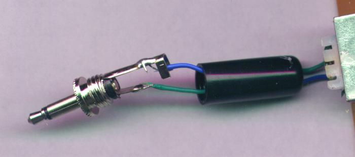
Plug the phone plug into the earphone jack of a convenient sound source, such as a transistor radio, tape player, or CD player.   

Plug the batter into the batter clip.   

Hold the transmitter near an AM radio, and tune the radio to 1000, so you can hear the your sound source in the AM radio. Adjust the volume controls on the sound source and on the AM radio to get the best sound.   

Without any connection to an antenna or a good ground connection, the transmitter will only transmit to a receiver a few inches away. To get better range, clip the ground wire to a good ground, such as a cold water pipe, and the antenna to a long wire, like the one we used for the crystal radio. Many countries limit the length of the antenna you are allowed to use without a license, so check with your local laws before using a wire more than a yard or two long.   

For a science fair project, the transmitter and receiver can be placed within a few feet of one another, and a short wire antenna should be just fine.   

How does it do that?   

The oscillator is connected to one end of a long wire antenna. It alternately applies 9 volts of electricity to the end of the wire, and then 0 volts, over and over again, a million times each second.   

The electric charge travels up and down the wire antenna, causing radio waves to be emitted from the wire. These radio waves are picked up by the AM radio, amplified, and used to make the speaker cone move back and forth, creating sound.   

The sound source (your CD player, or tape recorder) is normally connected to drive a speaker or earphone. It drives the speaker by emitting electricity that goes up and down in power to match the up and down pressure of the sound waves that were recorded. This moves the speaker in and out, recreating the sound waves by pushing the air in and out of your ears.   

Hosted by www.Geocities.ws

1