If a crystal radio is the distilled essence of a radio, this transmitter is the matching distilled essence of transmitters.
The transmitter goes together in about 10 minutes, and is small enough to fit in the palm of your hand.
Depending on the antenna, the transmitter can send voice and music across the room, or across the street.
I put together my first version with simple clip leads (no soldering, no printed circuit board, not even a battery clip). This version is much sturdier and convenient

Our transmitter will need these parts:
A one megahertz crystal oscillator
This is a crystal clock oscillator such as those used in computers.
There are many suppliers, such as Jameco (part #27861)
An audio transformer
This is a 1000 ohm to 8 ohm audio transformer, such as Radio Shack #273-1380.
A generic printed circuit board
I used Radio Shack's #276-159A, but any general purpose printed circuit board will do.
A phone plug
This should match the jack in your sound source. I use a 1/8 inch (Radio Shack #274-286A) plug to match standard earphone jacks of transistor radios and Radio Shack's Archer mini-amplifier speaker.
A 9 volt battery clip
I like the Radio Shack heavy duty type, part number 270-324. A 9 volt battery .
A set of alligator jumpers.
Radio Shack part number 278-1156, or you can find them anywhere electronics parts are sold.
Some insulated wire for an antenna
You can use the same antenna you used for the crystal radio.

The oscillator is the heart of the transmitter. It has four leads, but we only use three of them. When the power is connected to two of the leads, the voltage on third lead starts jumping between 0 volts and 5 volts, one million times each second.
The oscillator is built into a metal can. The corners of the can are rounded, except for the lower left corner, which is sharp. This indicates the where the unused lead is. The lead is there to help hold the can down firmly on the printed circuit board, but it is not connected to anything inside the can. The other main part is the audio transformer . In this circuit it is used as a modulator. The modulator changes the strength of the radio waves to match the loudness of the music or voice we want to transmit.
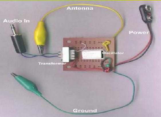
A pictorial diagram of the transmitter looks like this:
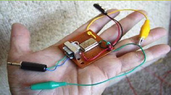
photograph of the completed transmitter is shown below
The transformer has two leads on one side, (red and white in the photo ) and three leads on the other side (blue, black and green in the photo).
The two leads are the low impedance side of the transformer, (the 8 ohm side). The three leads are the high impedance side (the 1000 ohm side). The middle of the three leads is called the center tap, and we won't be using it in this circuit.