A crystal radio is nice because it needs no power, and the materials can all be home-made or at least found around the house. But the crystal radio needs a big antenna, and a good ground, and so is not very portable.
To get away with using a much smaller, portable antenna, we will need to amplify the tiny signal it receives. This requires a portable power supply, such as a battery.
Our next toy is a portable radio. It can be powered from a tiny 1.5 volt battery, or from a battery made from copper wire and aluminum foil sitting in a glass of lemonade, a soft drink, or a beer, or by a few small commercial solar cells.The heart of the radio is a special 10 transistor integrated circuit in a tiny three-legged bit of plastic. This circuit comes ready-made with several amplifiers, the detector, and an Automatic Gain Control circuit that boosts the level of faint stations to match the strong ones, so no volume control is needed. The final radio has excellent performance, pulling in weak stations, and preventing nearby strong stations from overwhelming the weak ones next to them on the dial.
We call the radio a "Three Penny" radio because we use three shiny pennies as anchors for the various parts the radio needs. This makes the construction very easy.
If you have never soldered anything before, this is a great project to start with. It is very forgiving of the type of soldering usually done by beginners, and all the parts are widely separated, making the job much easier than with other circuits. Soldering irons and solder are inexpensive tools you can find at a local electronics store such as Radio Shack.
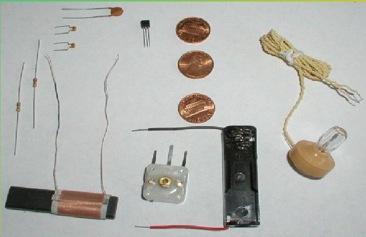
The three-penny radio needs these parts: Three shiny pennies You can clean them up with polish, or you can use brand new ones. A tuning coil You can wind one by hand, but in this project we use a much smaller coil with a ferrite rod inside. An MK484-1 AM Radio Integrated Circuit This is the heart of the radio. A Piezoelectric earphone A tuning capacitor We use a variable capacitor, from 0 to 160 microfarads. A 100,000 ohm resistor This resistor will have four colored bands on it. The colors will be brown, black, yellow, and gold. A 1,000 ohm resistor This resistor will also have four colored bands on it. The colors will be brown, black, red, and gold. A 0.01 microfarad capacitor This capacitor will be marked something like ".01M" or "103".Two 0.1 microfarad capacitors These capacitors will be marked something like ".1M" or "104". A 1.5 volt battery (optional) A 1.5 volt battery holder
We start by placing the three shiny pennies on an old board where we will work. An old board will not be missed if a hot soldering iron burns a black spot in it. Don't work on a nice tabletop.
The pennies should be clean and bright. This will help the solder stick to them and flow onto their surface. Solder will not stick to a dirty penny. I used clean relatively new pennies that I didn't have to clean or polish. Old pennies can be cleaned with brass polish or by simply leaving them in a mixture of vinegar and salt for a half-hour or so.
We are going to build the radio "upside-down", so that all of our soldering will be neatly hidden from view when we turn the radio over when we are finished. Select which side of the penny you want to be visible, and place that side face down. I chose "heads" to be visible, so the "tails" side is facing up in the next photo.
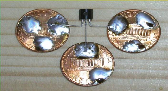
The first thing we will do is bend the wires of the integrated circuit so the outside wires stick out like the arms of a scarecrow. This makes the soldering much easier, since the wires are not close together.
The integrated circuit has a flat side and a rounded side. The flat side will face up when we are done, so we make it face down while we build our radio upside-down. The orientation of this part is important. The three legs are the "output", the "input" and the "ground" when it is upside-down like this. (When face up, the "ground" will be on the left, and the "output" will be on the right.) If the integrated circuit is not flat-side-down at this point, then we won't be connecting to the right parts when we are done, and the radio won't work.
It usually takes a while to heat up a penny enough to melt solder onto it. Hold the soldering iron firmly on the spot on the penny where we want the solder to be, and feed the wire solder onto the hot penny as it melts. It doesn't take much solder. It is often a good idea to make a small blob of solder on the penny first, and then place the wire of the integrated circuit onto the blob of solder, and reheat both until the solder wets the wire.
You will see that we have done just that in the photo. The two top pennies have three blobs of solder on them, and the bottom penny has two blobs of solder.
Solder all three of the wires to the three pennies.
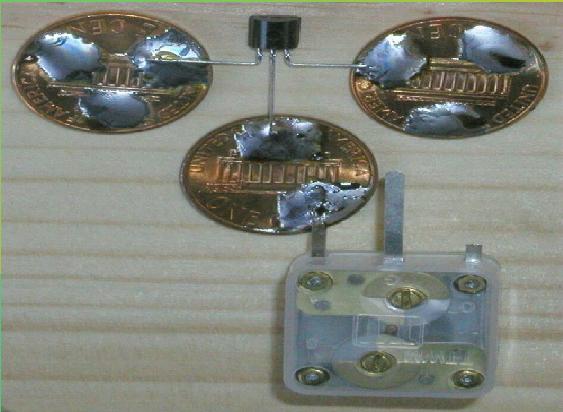
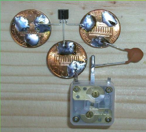
The next step is to solder the variable capacitor to the bottom penny. Remember to place the variable capacitor upside down. The variable capacitor has three legs, but we will only be using two of them. This variable capacitor is actually two capacitors in one, and they share the middle leg.
We will only be using one of the capacitors. The two capacitors have different values, and we are using the 160 microfarad side (the left in the photo) and leaving the 60 microfarad side unconnected. As the photo shows, I have cut off the third leg to remind me which side to use.