Radio QRP - The Art of Low Power and Clandestine Operations


Radio QRP
Radio QRP - The Art of Low Power and Clandestine Operations
Uppdated:
2005-11-20
NEW Sorry, if this site is temporarily unavailable! The site has become very popular with many visitors so the site can sometimes exceed its allocated data transfer. Then most of the pictures will not be shown!
FCC Enforcement Action Summary: 2005
The CORSAIR transmitter
was designed
by Dave Martin of W.N.K.R.
The original Grenade Transmitter
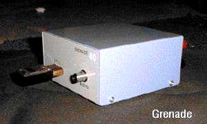

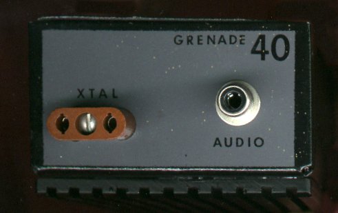
Grenade
History
by Grenade Radio (Boomer
The Dog)
2003 marks the 10th year of the Grenade radio. The first Grenade was built in Texas USA from surplus and bought parts, early in 1993.
The idea had its base in an amateur QRP transmitter called the "Two-fer" that Sparky of K-Zap radio had built in the late 1980s. This one watt kit was intended for Morse code use, and it didn't have a modulator circuit, but it was a complete shortwave transmitter on a 2 by 3 inch circuit board. Radio Animal modified the Two-fer and added a one-transistor series modulator then put it all in a small metal project box with audio and antenna connections to the outside. It wasn't perfect, but the concept of a one box, 12 volt transistorised transmitter got its start with that little rig.
A while later, a new design was started, and this time it was fully based on the classic and dependable high-level modulation technique that AM broadcast transmitters have used for years.
The first shortwave Grenade type transmitter was built for the 20 meter band, where crystals were available for testing, and because it was suggested that a higher frequency band might be a better choice for portable operation. Smaller antennas used at the higher frequencies can be easier to store and transport, and less height is needed to mount them, and yet still get an effective signal in the air. The case for this first Grenade was a used aluminium box that had been the former home of a FM amplifier.
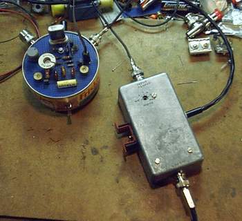
At testing stage, the beta version of this transmitter's radio frequency section was built on a 2x2 inch copper clad circuit board, using point to point wiring, and very tight construction! For testing, a voltmeter, ammeter, and a field-strength meter with a probe was used to measure the RF signals at different points of the circuit.
One of the plans was to do away with any kind of external modulator, because a single unit transmitter would be more reliable, easier to use, and it would get rid of extra connections in the system.
The modulator is an audio amplifier circuit that adds sound to the station's signal, had to put out about 10 watts and operate from the same 12 volt supply as the transmitter. We looked at schematics from CB radios, intercoms, and bullhorns, but those weren't quite right. New autosound systems operate from 12 volts, and the output stages are integrated circuits, so that would avoid having to build an entire modulator from separate parts.
There were no new autosound output ICs available in the lab at the time, so a junk car radio was opened, one of the output sections was circuit-traced and written as a schematic, carefully removed from the radio, and then rebuilt on a separate circuit board as a potential modulator for the Grenade. It worked well, after some modifications.
The car stereo was rated at 14 watts per channel, with outputs that were operated in bridged mode (balanced). This is an excellent direction to take for a simple modulator in this application, because it gives more audio headroom, so the same IC can be used as a modulator for higher power transmitters too. Many servo motor drivers ICs could also be adapted for use in this circuit as well. Current 40 meter Grenades don't use this type of modulator, because after tests, it wasn't seen as necessary for a 10 watt RF output.
The first test broadcast with the completed transmitter was done in late May 1993. The show was "The Voice of the Unknown Ghettoblaster" at 14975 kHz, playing music by Ice Cube and other Rap, along with announcements and funny comments by the operators about the FCC chasing after the station, which was broadcasting from the middle of the ghetto. The claimed location of 'Ghettoblaster couldn't have been further from the truth of where it really was broadcasting from! The test station's name was really appropriate, because it's unknown whether the broadcast was heard by anyone except the operators..
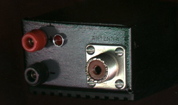
The name 'Grenade' came from several ideas, one was Ernie Wilson's publication of excerpts from 'Radio Is My Bomb' in his ERN newsletter, and the other was that the dummy load connected to an early 40 meter version of the transmitter sort of resembled a bomb or hand grenade, with the black colour and large finned heat sink.
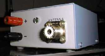
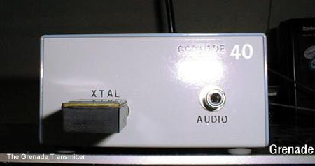
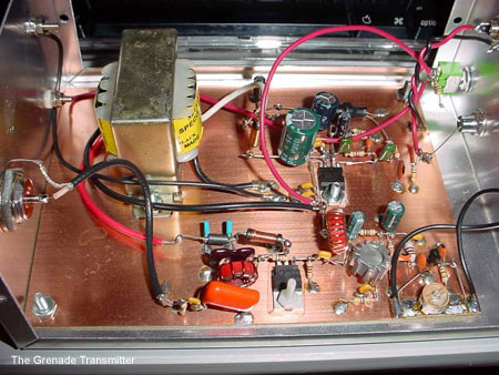
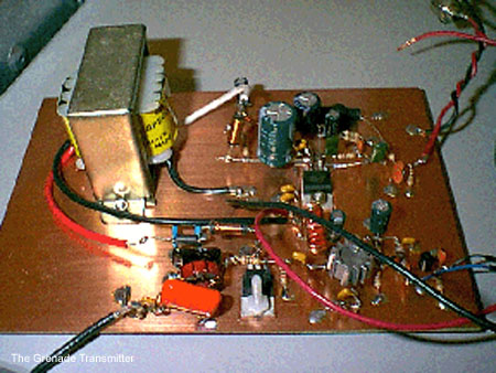
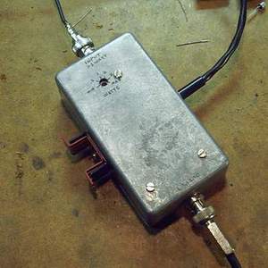
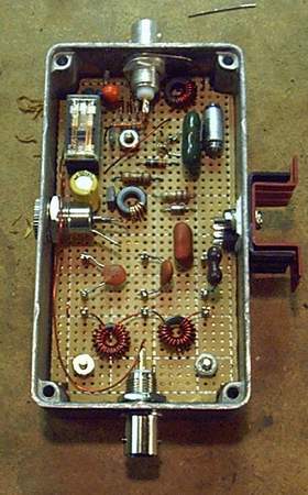
Inside The
Grenade Transmitter
Joe Bean Prototype Pictures


Requirements
- 12-14 volts DC power at 1.5 amps, 2 or more amps peak, to handle the modulation.
- Crystal FT-243 style case, in the 40 meter frequency area (6000-8000 Kilohertz).
- Antenna cut for the frequency of the crystal. A Dipole is the best and easiest.
- Audio source, .5 volts 'consumer level' like that from home tape decks, VCRs, or computers. A boom-box or other portable can be used through the headphone output jack.
Specifications
- Power output: nominal 10 watts @ 12.5 volts, 1.2 amps
- RF output impedance: 50 - 75 ohms
- Harmonics: -30 dB
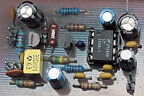
The Grenade
Project RF-section
The
"Grenade" is a 10 watt AM transmitter for the 40 meter
band (6955 kHz).
It was designed, built and sold by "Radio
Animal" of WKND.
The Grenade originally came built with one x-tal (6955/6950) and a dipole antenna at just under 100 dollars U.S. It is a great little radio, roughly the size of a brick, and weigh in at well under half a kilo. With a dipole cut to frequency you can cover the USA from the Rockies to the Atlantic in the evening under decent conditions. Output power roughly 15 watts when running from a 12 volt battery (That is constant carrier, it peaks in the 50 watt range) and will do close to 20 watts when powered from a regulated power supply. The limiter/compressor is really what makes the Grenade great. Makes it possible for someone with no knowledge of radio production to plug in a Walkman type tape deck and go on the air. The rig is cased is in a black steel box, with a finned aluminium heat sink covering the top. The transmitter can run continuously for 3 straight hours in hot temperatures (85+ degrees Fahrenheit) and the rig barely gets warm to the touch. Unlike ham transmitters, this one can run several hours per day with no problems and it is made so that it can handle running into mismatched or even no antenna.
The Grenade
Project LF-section
The
limiter/compressor is really what makes the Grenade great.
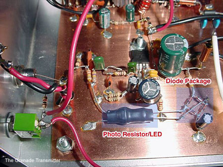
The limiter/compressor in the Grenade Project LF-section.
The Grenade has an automatic level control to keep the audio level from being too loud or too soft. The circuit tries to compensate for differences in input levels, but some sources might still be too loud or too soft. If using a portable, like a boombox or personal stereo, adjust it for an average listening volume through the speaker, then connect it to the transmitter.
A resistive optocoupler, comprising an LED coupled to a photoresistor, has some unique advantages when used as a control element in analogue audio circuits. The devices consist of a high performance LED shining on a photocell inside a light-tight case. It's a light source and a photoresistor pointed at each other and sealed in an opaque package. It's pretty easy to make a limiter out of one: put a resistor in series with the photoresistor and drive your signal across the pair. Take the output across the photoresistor. Drive the light source (usually an LED) such that when the output level is too high, the light goes on and when it's too low, the light is shut off. When the light goes on, the photoresistor's and the resistor divider's loss increases value drops => the gain of the photoresistor's value increases and circuits drops. When the light goes off, the voltage loss of the divider decreases, raising the gain. That's all there is to it...
The only subtlety is how quickly the light turns on and off (or becomes brighter or darker) as this and the decay time of the photoresistor itself determines the attack and decay time of the limiter. The photoresistor is a typical Radio Shack thing the size of a dime, which has the LED touching the lens and pointing directly into it, with the whole mess sealed in a mass of black heat-shrink tubing pieces to block outside light. The photocell has a dark resistance of about 10 Megs and a LED-full-on resistance of a few hundred ohms.
Simple Modulators for solid-state Transmitters: Simple AM modulator work by varying the amount of power supplied to the transistor, which is serving as the RF output amplifier. By imposing an audio waveform on the power supply, amplitude modulation is achieved. A transformer less circuit is physically smaller and lighter than designs that use a modulation transformer. Transformer-based modulation methods have a more "warm" sound quality, while transformerless schemes have a "crisp" sound.
Audio level control device (compressor).
by G3YXMStarting with an audio compressor. There have been umpteen designs for compressors published over the years but many of them are difficult to set up or cause distortion and others use expensive chips.
This one updates an old principal used years ago: a light bulb driven by audio illuminates an LDR in the feedback loop. The brighter the light tends to glow, the lower the resistance of the LDR becomes and the more negative feedback gets applied, reducing the gain. The LDR is purely resistive so the amplifier maintains good linearity.
The problem with a light bulb is its' thermal inertia, the attack time of the AGC circuit is too slow and you get distortion on peaks. What we needed was a fast light bulb.... We now have one, the light emitting diode!
The circuit is shown above and should cost about $15 if you have to buy all the bits new.
The NORP12 L.D.R has a dark resistance of around 1MegOhm but will come down to a few hundred Ohms in bright light. It's peak sensitivity is to yellowish light at a wavelength of around 580nM. The best match is, of course, a yellow LED. Toshiba have some nice bright ones with a peak output at 590nM which is close enough!
The crux of the thing is to mount the LDR and LED in close optical contact whilst being careful to exclude all stray light from the assembly. You can mounted them in a piece of black plastic tubing and sealed it with silicone rubber and black end-caps.
The op-amps are two halves of a TL072 and have enough gain to bring a mike insert up to a good loud line level. Performance has been measured as below.
Performance with gain set to Max.
Input level Output level theshold of compression 20uV RMS 1.9V RMS maximum input level 3mV RMS 2.6V RMS
40dB input range is compressed to 3dB output change.
Distortion is less than 0.2% within normal operating range.
Frequency response is 30Hz to 8kHz within 3dB at max gain.
The current drawn at 12V is only about 4mA.Specialised components
- Op amp Chip TL072
- Light dependant resistor NORP12
- Toshiba yellow ultra-high-bright LED
The resistors are nothing special, 0.4W metal film are OK; the diodes are small signal diodes such as 1N4148 and the capacitors are at least 12V working.
Do not attempt to operate the circuit below 12V as there won't be enough drive to the LED and clipping will result. Using germanium diodes instead of silicon ones would give a little more headroom (and slightly reduce the output level ).
Larry Sparks NØBHU is building a low power AM transmitter for 75 meters. It's not too often we see a transmitter with a big audio chip and a modulation transformer. Here is Larry NØBHU's 75 meter AM transmitter. The heat sink on the right rear is for the modulator and the final PA is on the left front. He is getting about 9 watts of carrier power output .!

LIMITER
from PiRa
Why it is important to use a limiter?
Audio signals as music or speech have big dynamic ranges. There are silent and loud sections. These audio signals aren't too good for a transmitter, which requires audio signal with constant level on the input. Limiter is a device, which weakens loud signals and intensifies silent signals. On its output there is signal with constant level.Technical specifications
Supply voltage: 10-14 V stab.
Supply currents: 20 mA
Audio input: impedance 20 kOhm, optional preemphasis
Output voltage: 0,4 V rms
Dynamic range: >50 dB
Output
voltage vs. input voltage
Schematic diagram

Parts list
Resistors:
R1 - 68 k
R2 - 22 k
R3 - 180 k
R4 - 10 M
R5 - 10 k
R6 - 47 R
R7 - 240 k
R8 - 1,5 k
R9 - 820 RCapacitors:
C1 - 100 p (ceramic)
C2 - 1 n (plastic)
C3, C6, C12 - 100 n (ceramic)
C4, C11, C13 - 100 u (electrolytic)
C5 - 0,33 u (tantalum)
C7, C8 - 10 u (electrolytic)
C9 - 220 n (plastic)
C10 - 47 n (ceramic)
C14 - 470 n (plastic)Misc.:
T1 - BF245C
T2 - BC556B, BC307
IC1 - LM386
PCB layout
"NWQRP
Special" 30mtr 5w CW TX
KG7CR

The transmitter is shown in an aluminum box with an FT-243 crystal socket and key jack on the front. There are 2 RF jacks on the back, an SO-239 type for the antenna, and a BNC for the antenna output to the RX via a PIN diode switch that is not shown.
The circuit uses an NPN transistor oscillator, 2N3866, 2N5103 or 2N2219 transformer coupled to an IRF510 Pwr FET as the RF amplifier. A two section output filter is used. The PCB supplied by NWQRP Club was thoughtful in it's design and lent itself easily to future modifications. Common modifications were sidetone, TR switch, and keying characteristics.
At WB6FZH a second transmitter was built with switch to change the output filter for other bands. The broadband design lent itself easily to other frequencies. At 12 volts the output is a solid 5w. Bruce Franklin, the designer, NWQRP Technical Editor & Father of the QRP+, said that if you increase the IRF510's supply voltage to 18 volts, that almost 18 watts is availiable to a properly heatsinked output stage.
This is
another Grenade Transmitter ...
by Radio Anarchy
The Parts List for the Shortwave Transmitter:
- R1 - 33K ohms, ¼ watt, carbon.
- R2 - 4.7K ohms
- R3, R6 - 100 ohms
- R4 - 22 ohms
- R5 - 100 ohms, 1 watt, or greater.
- C1 - 47 to 470 pF, or greater, silver mica or disc ceramic. Better yet, a trimmer capacitor, to slightly change frequency ±1 KHZ.
- C2 - 10 to 140 pF trimmer.
- C3 - 100 to 220 pF, silver mica or disc ceramic.
- C4 - .01 to .05 µF.
- C5 - 300 - 800 pF, or (? ? ?) variable capacitor. Use an Arco TC-4610 (260-900 pF) compression trimmer.
- C6 - .01 to .1 µF.
- C7 - 1000 µF or greater, electrolytic, 25 volts or greater.
- X1 - Fundamental mode crystal, 5 to 8 MHz.
- T1 - On an Amidon T50-2 toroid core, primary is 26 turns of #28 magnet wire closewound, secondary is 2 turns wound over the primary windings.
- T2 - On an Amidon T50-2 toroid core, bifilar wind 6 to 8 turns of #18 magnet wire. See note 1 for details.
- L1 - 2 mH or greater, .5 ohm or less resistance. Use the inductor from Radio Shack p/n 270-0030A HD Noise Filter. One could also use the 4 or 8 ohm secondary of a medium sized audio transformer, or the secondary side (6 to 24 volts) of an AC mains power transformer.
- L2 - .7 µH. Wind 7 turns of #16 magnet wire on a 5/8 inch diameter form, then remove form.
- L3 - 1.4 µH. Wind 11 turns of #16 magnet wire on a 5/8 inch diameter form, then remove form.
- Q1 - 2N2222
- Q2 - 2N2907
- Q3 - IRF510 or IRF511 (Radio Shack p/n 276-2072A)
... and this is another Audio section without compressor/limiter
A slight modification in the LF/RF section of the Grenade transmitter
How to winding and installing a Toroid Coil
The transmitter's low-pass filter uses a high-Q toroid inductor wound on a T37-2 form (T37 means the powdered-iron form is .37-inches in diameter). When winding the Toroid Coil, the numbers of turns are counted inside the form (not on the outside). That means, if the instructions call for a 12-turn coil, you must pass the wire through the centre of the core 12 times. When winding this coil, be sure to pull each turn up tight before starting the next. If the coil is wound loosely, its inductance increases - a condition that may reduce transmitter output power. Count turns on inside of form. Tin leads with solder before installing. Pull each turn tight before winding the next. Finally, before installing the Toroid Coil be sure to tin both leads with solder. The coil wire is coated with heat-strippable enamel insulation that breaks down at soldering-iron temperatures. If you touch the tip of an iron to the end of the wire for several seconds, the insulation should start to melt, allowing solder to adhere to the copper underneath. If your iron is not hot enough to start this process, carefully scrape the insulation off with a small hobby knife and tin. If necessary, refer back to these instructions at any time during assembly.
Simple Class E Transmitter
Class E amplifiers are very efficient amps and are generally built with MOSFET transistors. The principle is to drive the MOSFET's gate input with square waves to quickly put the device into it's low ohmic region and to do this when the voltage across the drain of the MOSFET is at or near zero volts. This greatly reduces the heat dissipated by the MOSFET and increases efficiency. A choke value for the drain is chosen so that it resonates at the operating frequency, in combination with the parasitic capacitance of the drain and the output filter. The "fly wheel" effect of the resonant tank causes the drain voltage to drop to zero before the MOSFET is switched back on. Efficiencies of 70% or more can be achieved this way.
The circuit show below is a simple Class E transmitter and is shown built for 40 meters. It uses a 74HC02 NOR gate as a crystal oscillator. The other three gates in the package are used to gate the clock signal to the output MOSFET. The crystal oscillator can also be used with a direct conversion receiver. An Rx offset curcuit is shown to shift the oscillator frequency when receiving.
A 2N7000 is used for the final power amp. Although only one is shown, three '7000's are used in parallel to reduce the "on" resistance, which inproves efficiency. 70-75% efficiency can be achived. The amplifier delivers about 2 watts output with a 9 volt supply and about 4 watts with a 12 volt supply. The plastic TO-92 2N7000's bearly get warm to the touch.
For best results the spacing on the output filter inductors with need to be "tweaked". Monitor the drain current and output power and calculate efficiency. Adjust the spacing of the windings on the output filter inductors until you get the best efficiency. L2 will have the greatist effect. L5 and C15 are used to suppress VHF spurs, which aren't effectively attenuated by the HF low pass filter.
If the square wave drive to the fet is simply gated on and off, the keying waveform is very steep and causes key clicks. Therefore, the supply voltage to the PA needs to be ramped up and down in order to provide for a least some wave shaping. Q1 is a PNP power transistor which is turned on and off by Q2. C19 slows the turn on and turn off time down and causes the voltage on the collector to rise and fall with about a 5 ms time constant. R5 and C14 form a delay to keep the drive active to the PA while the supply is ramping down.
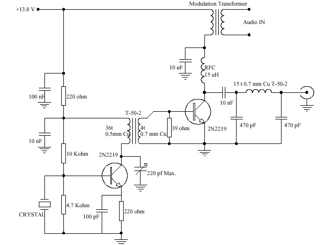
A small two
stage transistor AM transmitter
by Free Radio Beacon
This is two-stage transistor AM transmitter for the shortwave band, which gives about 1 watt in output. You can use a 2N2219 or a 2N3553 in the final stage. The output with a 2N3553 is aprox. 1.8 watt @ 12 Volt. The transmitter seems to give more output when you use 7 turns instead of 4 turns in the secondary section of T1 (the coil between oscillator and final stage). It will work fine between 6 and 8 MHz. Try with different (power) transformers to modulate the transmitter in Amplitude Modulation. You have to do experiments to find a suitable modulation transformer to produce a good Amplitude Modulation.
Also test with different transistors in the final stage, but be careful to not blow up the rig.
- BD135 - gives 1.7 watt output @ 13.8 volt
- C2314 - gives 2.4 watt output @ 13.8 volt
- BLY88C - gives 3 watt output @ 13.8 volt
The "Talking" Pixie2 QRPp AM Transmitter
The Pixie2 is a simple QRP CW transmitter that dozens of ham radio operators have successfully built.The Pixie2 is usually built for the 40 meter band but it will work on frequencies from 1000 kHz up to at least 15 MHz. It is said to output a couple hundred milliwatts of RF.
The circuit can be amplitude modulated quite easily. A small audio amplifier feeds audio current into the 8-ohm side of a transformer. The 1k ohm side of the transformer is inserted in the V+ supply going to the Pixie's output transistor.
This modified Pixie2 is called the Talking Pixie. It has 18 components (not counting circuit board, jacks, power supply and external audio amp). Building it on a prototyping board only takes a few minutes if all the parts are available.
The level of the audio fed to the transformer is adjusted until the best sound quality is achieved. The Talking Pixie will not sound as loud as commercial stations but the user must avoid the temptation to over-modulate; nobody will listen to an over-modulated signal.
parts list
C1: 100 pF
C2: 220 pF
C3: 82 pF
C4: .01
C5: .01
L1: 150 uH
L2: 22 uH
Q1: 2N2222 or 2N3904
Q2: 2N2222A (metal can type) or 2N3866
R1: 47K
R2: 1200
R3: 33K
R4: 10 or 15 ohms (experiment!)
T1: 1000 ohm to 8 ohm audio transformer
The frequency is crystal-controlled. A crystal for the frequency you're interested in will have to be ordered if you don't have one handy.
The transformer must be rated to handle at least half a watt of audio; a very tiny transformer will not sound good and will have too much resistance on the 1K winding.
L3, C6 and C7 form a low-pass filter to attenuate the harmonics generated by the circuit.
Specific values for various frequencies can be found on on this site on special filter schematic.
L1 and L2 are factory-made axial molded chokes.
Variations
The impedance and bandwidth of the antenna will affect the sound quality of AM transmitters like the Talking Pixie. What sounds good on the test bench with a 50-ohm dummy load attached to the output might not sound as good with real-world antennas like short end-fed wires. Some kind of antenna tuner might be helpful. (By the way, two 100-ohm resistors in parallel make an adequate dummy load for this rig.) Needless to say the size and efficiency of the antenna will have a major impact on the range.
If you build the circuit on a prototyping board, you can experiment with many variations on the circuit design.
Here are some modifications that have been suggested...
Martin Spencer suggested using a FET (such as 2N7000) instead of an NPN transistor for Q2. This could give more linear modulation. Replace L1 with a 5K variable resistor; remove the crystal for a moment and adjust the resistance for about 2 mA drain current
Mark Weiss wrote: "You can put another transistor in series with the PA and use it as a series voltage source. By varying this voltage control element with the audio signal, highly linear modulation is achieved. Transformers tend to present variable impedances, causing the PA to be less stable under varying load conditions. A direct-coupled modulator can offer the potential for great tolerance of loads that aren't precisely +50 j0."
Other QRP CW transmitters can also be modified for amplitude modulation. You will find schematics for such transmitters in ham radio books and magazines, and on websites operated by QRP clubs.
Steve Quest's Transmitter
by S.QuestIn various newsgroups Steve Quest has described an AM transmitter for mediumwave and shortwave that has produced great results and is quite inexpensive. Here is the verbal description he offered:
However, for now, just picture a standard Pierce oscillator, crystal controlled on your frequency of choice, with the output connected to a standard class C amplifier stage. The only modification to the standard class C amp stage is the insertion (series, so cut the trace and insert) of a modulation transformer between the power supply line and the isolation inductor on the collector. What works great is the $1.95 at my local audio shop, SPECO line matching transformer. Connect the transformer backwards! In other words, the input side goes to the class C amp, and the output side, normally the side connected to the speaker becomes input. Transformers work both ways you know.
Use the 500 ohm and common taps on the class C amp side, and the 8 ohm and common tap on the input side.
Now hook up a power audio amplifier to the (now) input of the transformer, and a mic or other audio source to the line input of the power audio amp. Adjusting the volume on the audio power amp will increase and decrease your MODULATION! Use a scope to set your modulation, just lay the probe near the antenna to see the AM waveform. Adjust to about 80% modulation, don't overmodulate, it sounds like crap AND is quite inefficient.
*IMPORTANT* Use a chebichev filter between the output of the class C and your antenna! If you don't your harmonics will be over a watt for sure!
This configuration, when powered by 12 volts will generally give you an input power of about 5 watts. That's based upon the class C amp giving you a times 10 gain, and the input power from the Pierce oscillator of half a watt. Sloppy design of the Pierce, and poor tuning on the class C will cause the power to go DOWN. However, if you're good, you can get 10 watts or more by tweaking the Pierce up to a 1 watt output into the x10 class C stage.
About a 4 to 5 watt input signal to a 150 foot random-wire antenna on the 41 meter band during the average sunny winter day resulted in a clear signal copied at greater than 200 miles and a weak signal copied at 1000 miles. This range example is reproduceable by several successful tests.
And here is the schematic:
Parts List:
R1 = 47k 1/4w
C1 = .001uF
C2 = 470pF
C3 = 470pF
C4 = 100pF
C5 = .01uF
C6 = 470pF
C7 = 820pF
Y1 = 7.3728 Mhz series type (off the shelf, CPU application)
Q1 = ECG or NTE282 or similar
Q2 = ECG or NTE235 or similar
T1 = Speco type T7010 70 volt line matching transformer
L1 = 28turns around 1/4" ferrite overwrapped with 9turn secondary
L2 = 28turns around 1/4" ferrite
L3 = 1.5uH choke
To make L1, tightly wrap 28 turns, then wrap 9 turns over that tomake the secondary. Space the windings out to evenly cover thefull length of the 28 turns. Use light gauge enamel wire for all.
To connect the modulation transformer, wire backwards using the normal secondary as the primary. Connect the red wire of theinput side to Vcc and the black wire to the class C amp choke. Connect the output side white wire to the amplifier speaker jack positive, and the black wire to the speaker jack negative. Use the amplifier volume control to adjust modulation level.
A few more details of this circuit:
... since the rig operates in the 41 meter band, I just used generic CB radio transistors. The Pierce oscillator uses a generic CB radio driver transistor, and the final is a CB radio final. Thesetransistors are cheap, readily available, and probably will never beoutlawed (like I suspect VHF RF components will eventually be). Since CB radio is 27 Mhz, running them at 41 meters (7 Mhz) is very easy on them.
Any type NPN, TO-220 package CB radio driver and final will workfor this application. There are probably _better_ transistors out there,but these are cheap, available at the local radio shop, and already instock for those of us who fix a few CB radios from time to time.
And here's some additional detail:
I get my forms from a distributor, and my inductors as well. However, I know there are ferrites that are "close enough" in the Radio Shack assortments. You should be able to find one fairly close.
The question this time is could one substitute say 5/16" core for L1 & L2 and adjust the windings to come out with the same results. If the answer is yes, then could you recommend a good starting point to make the alterations?
Sure, use a 5/16" core, and the same number of turns. Remember, I didn't specify the wire gauge, and I should have said "about 1/4" ferrite rod" instead of being exact. Use a heavy enough enameled wire that you don't vaporize it with current flow, I used the middle gauge out of the Radio Shack 3 pack for my windings. This fact should probably be added at the website. :) You may have to adjust secondary turns between the oscillator/driver and the final to tune for maximum power. Don't glue the windings and leave plenty of extra (not looped but curved up) so you can do that. Once you find the right amount, glue them down. I use wax usually, but have also used shellac, varnish, silicone, you name it.
On the inductor in the final, an extra few turns will not hurt, but don't take away! Same goes for the primary on the osc/driver. However if you add turns, you'll have to adjust the secondary turns and capacitors. One thing to remember with HF verses VHF, the windings are NOT as critical. 3 turns in an air wound VHF oscillator tank coil will get you, let's say 88 Mhz, and one more turn and you're down to 64 Mhz, and another and you are in the 40's. It isn't like that with HF, it's not so touchy.
The NB6M Miniboots
By Wayne
McFee NB6M
Requests for an “outboard” version of the RF power amplifier used in the 5 Watt Mod for the SMK-1 led me to further research and experimentation which resulted in the amplifier circuit described in my article “A Mosfet QRP Gallon”, published in the Fall, 2000 issue of QRPp, the journal of the NorCal QRP Club. The RF amplifier described utilized the cheap, readily available IRF510 Mosfet to produce 5 Watts of output with an input of from 1 to 1.5 Watts and was switched into and out of the antenna line from the QRP rig by a DPDT toggle switch.
Since that article was published, I have added several improvements to that basic RF Amplifier circuit. I call the new amplifier the “NB6M Miniboots”. For those who are comfortable with building “Ugly Style” from a simple circuit, this project is a snap and the parts are all readily available. For those who would like the parts already gathered and the layout prepared for them, a kit is in the offing.

40/20 Meter version shown, with attenuator input for 1 to 2 Watts drive

40 Meter version
shown, with transformer input for 3/4 to 1 Watt drive
This RF Power Amplifier operates from a 12 Volt supply, can be set up to accept an input of from about ¾ Watt to 2 Watts, and can deliver from 10 to 14 Watts of output into a 50 Ohm load. Tests thus far have been very satisfactory on the 80 through 20 Meter ham bands, with output typically 14 Watts or more on 80 and 40, a bit lower on 30, and around 10 Watts on 20. Initial tests on the higher frequency bands indicate that some circuit changes may be necessary in order to provide for operation of the “Miniboots” on 17 through 10 Meters. Further tests are in progress.
Just as Rick Campbell, KK7B, called his small, high performance CW transceiver the GQRP Rig, or Generic QRP Rig because it incorporated ideas from previous generations of homebrew artists, this amplifier circuit could be called the GPA, or Generic Power Amplifier because it makes use of ideas from contributors like Michael Masterson, KA2HZA, Mike Kossor, WA2EBY, and from such all-time greats as Wes Hayward, W7ZOI, Roy Lewallen, W7EL, and Doug DeMaw, W1FB.
The additions to the basic QRP Gallon circuit include an RF-sensing relay driver circuit to switch the amp into and out of the antenna line automatically, output network filter values to allow for up to fourteen Watts of output with a two watt input, and a drive level adjustment potentiometer which allows for setting the amplifier at exactly the 5 Watt “QRP Gallon” level as desired.
Mike Gipe, K1MG, performed spectrum analysis tests on a 40 Meter version of the “Miniboots”, which showed the output of the amplifier to be quite clean at all levels of drive and output.
On-the-air tests of the “Miniboots”, involving many QSOs on the 40 and 20 Meter ham bands, using an SW-40 and an SW-20+ as the driving QRP rigs, have resulted in signal reports such as “nice sounding rig”, “very clean sounding rig”, and “your rig sounds great”. Monitored on another receiver, the output CW note is pure, and the keying very clean.
For a driving power level of from one to two watts, the amplifier utilizes a resistive 3db attenuator at the input, in order both to provide a 50 Ohm load for the driving rig and to prevent over-driving the amp. If the driving QRP rig has an output of three-quarters to one watt, a broadband transformer input is used which provides close to a 50 Ohm load to the driving QRP rig without attenuation.
A simple DPDT toggle switch allows for two-band operation. A multiple-position rotary switch could be used to select output networks for multiple-band operation, if desired. The addition of an RF-sensing relay driver circuit provides for hands-free T/R switching. The timing of the relay driver circuit is such that there is full QSK for the slower CW speeds and semi-QSK for the medium to fast CW speeds. The relay used pulls in quickly enough that, even at the faster CW speeds, a single “dit” is not clipped short. Although the relay specified in the circuit diagrams is Mouser part # 431-OVR-SH-212L, a 12 Volt, DPDT relay with a 900 Ohm coil, a Radio Shack 12 Volt DPDT relay with a 200 Ohm coil, Radio Shack part # 275-249A, has been used very successfully in this circuit.
Thus far, several versions of the Miniboots have been built and tested, by the author and by Richard Fisher, KI6SN, with similar, positive results. All versions have been built “Ugly” style, as there are a relatively small number of parts in the amplifier circuit, and, building the amplifier over a solid ground plane, with short leads, improves stability and helps prevent spurious output. Thus far, there has been no indication of instability in any of the prototypes built.
None of the versions of the “Miniboots” built thus far have been laid out exactly the same, due to the “ugly” method of construction. However, that means that the individual builder can plan the layout so as to utilize any of a variety of enclosures. One possible layout is suggested in the attached drawing.

A parts list and two circuits diagrams are provided, one with the resistive attenuator input to accept one to two Watts of drive, and another with the broadband transformer input to accept a drive level of three-quarter to one Watt.
If the broadband transformer input is used, insert a QRP SWR meter in the line between the driving rig and the amplifier and check the reflected power back to the rig. My antenna analyzer shows the amplifier with the transformer input to have an SWR of 1.3 to 1 or less from 1.8 Mhz up through 10 Mhz. At 14 Mhz, the SWR is 1.7 to 1. The number of turns on the primary of the broadband transformer can be adjusted as necessary in order to provide a better match.
The IRF510 will require heat sinking, and the Drain of the Mosfet must be insulated from ground. It is a good idea to use an Ohm-Meter to check for shorts from the Drain to ground before supplying DC power to the amplifier. The Miniboots could easily be built into an Altoids tin, if desired, making for a very small package.
The drive level adjustment pot can be either a trimpot, with a screwdriver access hole cut in the enclosure used, or can be a front panel mounted control with a knob. The choice is yours. Whichever style pot is used, the input circuit should be laid out so that short leads are used to connect the pot to the gate circuitry of the Mosfet. Also, if considerable operation is planned at Milliwatt levels, the pot should have a high enough wattage rating to be able to absorb its share of the RF input to the amplifier.
Two component value charts are provided for the output filter network.
Table 1 has component values for ten to fourteen Watts of output.

TABLE 1
Table 2 has component values for a nominal 5 Watt output, should the builder desire to build the amplifier for use only up to the QRP Gallon level.

TABLE 2
An automatically switched, outboard RF Power Amplifier which allows for operation at power levels from Milliwatts to several Watts is a very useful addition to the QRP ham shack.
MiniBoots Parts List
.1 uf 4
.01 uf 1
.001 uf 2
2.2 uf Electrolytic 1
100 uf Electrolytic 1

100 Ohm trimpot or panel mounted pot, as desired 1
33 Ohm, ¼ Watt 1
2.7 Kohm, ¼ Watt 1
10 Ohm, ¼ Watt 1
1 KOhm, ¼ Watt 1
4.7 KOhm, ¼ Watt 1

12 Volt, 1 Watt Zener Diode 1
1N914 (or 1N4148) 2
1N4004 Silicon Diode 1
2N3904 General Purpose Transistor (2N4401, etc) 1
IRF510 Mosfet 1

RF Choke, FT37-43 with 5 Turns # 22 1

12 Volt, DPDT Relay
 Mouser # 431-OVR-SH-212L or Radio Shack RS275-249A 1

RF Jacks, BNC Type 2

Power Connector 1

For resistive attenuator input
10 Ohm, 1 Watt 2
150 Ohm, 1 Watt 1

For broadband transformer input
FT37-43, Primary 6 Turns # 24, Secondary 4 Turns # 24 1

If two-band operation is desired, add
DPDT Toggle Switch 1
If multiple-band operation is desired, add Rotary switch, dual contact, multiple-position as desired 1 For output filter component values, see Tables 1 and 2 Enclosure as desired.
5 Watt (QRP
Gallon) Power Amplifier
by
KD7REM
The circuit design I used for this is courtesy of Wayne McFee NB6M and he calls it the
"NB6M Miniboots" and it is now available from NorCal as a kit.
I needed something to get more oomph from my Tuna Tin 2 and since it was running on 40 Meters that's what I built this for.
The heart of this amp is the IRF510 Power Mosfet Transistor. If you have Acrobat Reader here's the Data Sheet: IRF510.pdf Otherwise just believe me that it's a usefull little gadget. (They're also available at Radio Shack for a little over a dollar.)The band and power output level for this design is determined by the output LC network. (see tables on NB6M's page.) I used solder turrets to mount the caps and coils so it would be easy to change them out. I'm going to explore the possibility of fitting them on a 14-pin DIP header. That would be cool.
The circuit is very simple, here is a different way of looking at it without the RF sensing relay-bypass portion:
The RF-sensing Relay-bypass circuit responds very well. I used an Omicron I had kicking around that had a coil resistance of 322 ohms. It fits in a 16-pin IC socket so I put a rubber pad on the lid to keep it from "dit-dah-ing" out..
I mounted the drive trimpot on the bottom of the circuitboard and drilled a hole in the top of the enclosure to access it.
Here it is setup for action with the Tuna Tin. NB6M says it requires 1 watt to drive this thing. My Tuna Tin puts out about .7 watts and has a bit of harmonic distortion. This baby cleans it right up! And I get a little more that 5 Watts to boot! (Maybe that's why he called it MiniBoots?)
BUILD A 5
WATT 40 METER CW TRANSMITTER
by Ranson
Build a 5 watt, 80 meter QRP CW Transceiver!!!
Try to convert
this one to an amplitud modulated transmitter
and inform us of the modifications and result.
There is nothing more satisfying about this hobby than building your own transmitter. The circuit in figure below is a crystal controlled CW transmitter with at least 5 watts of power. This circuit is built on a Radio Shack universal board (276-168B) and worked extremely well the first time on the air. This circuit is unique in that it uses a power mosfet as a final rather than a conventional bipolar transistor.
The advantages are as follows:
- Very high gain with almost 90% efficiency. (Only a small heat sink is required.)
- Resistant to high SWR. 30 second key down with no antenna resulted in no damage.
- Power mosfets do not exhibit thermal runaway as with bipolar devices.
The disadvantages are that a bias voltage is required because the Gate threshold voltage can be anywhere between 2 and 4 volts for any power mosfet. This bias must be adjusted for the particular transistor installed in the circuit. In addition, a Zener diode is required to insure that the Gate voltage never exceeds 20 volts. This circuit proves that the advantages far outweigh these requirements.
The adjustment of the bias voltage is critical and is adjusted by first turning R10 so that zero volts appears on the Gate of Q4. Install an ammeter to the 13.8 volt supply voltage and apply power. At this point the circuit should only be drawing just under 1 milli-amp. Now turn R10 slowly until the ammeter reads about 5 milli-amps. This adjustment should never exceed 10 milli-amps. Turning R10 up too high can cause damage to the power mosfet. Once adjusted, R10’s setting remains the same unless Q4 is replaced.
All transistors can be purchased at Radio Shack and should not be substituted. Crystal Y1 is a 7.040 MHz crystal and can be purchased from Dan’s Small Parts & Kits or from Doug Hendricks. A small heat sink is required for Q3 and Q4. S1 switches between transmit and receive modes so that no damaging RF gets to the receiver being used. The frequency is fixed but a trimmer capacitor can be installed in parallel or series with Y1 to allow some adjustment of frequency. Toroids can be purchased from Dan’s Small Parts & Kits or from Palomar Engineers.
Parts List
- R1 5.6K Resistor (Green, Blue, Red) ¼ watt
- R2 15K Resistor (Brown, Green, Orange) ¼ watt
- R3 2.2K Resistor (Red, Red, Red) ¼ watt
- R4,R8 1K Resistor (Brown, Black, Red) ¼ watt
- R5 4.7K Resistor (Yellow, Violet, Red) ¼ watt
- R6 22 ohm Resistor (Red, Red, Black) ¼ watt
- R7,R9 10K Resistor (Brown, Black, Orange) ¼ watt
- R10 10K Trimmer pot, ¼ watt or larger
- C1 .01uf Ceramic disk capacitor
- C2,C4,C6,C9 .1uf Ceramic disk capacitor
- C3 .0028uf Ceramic disk capacitor (Use two .001uf capacitors and one 820pf capacitor in parallel.)
- C5 68pf Ceramic disk capacitor
- C7,C10 .001uf Ceramic disk capacitor
- C8 100uf electrolytic capacitor. (observe polarity)
- C11,C13 390pf Silver Mica capacitorC12 820pf Silver Mica capacitor
- D1 15 volt Zener diode. 1N4744 or similar
- Y1 7.040 MHz or 7.122 Mhz crystal
- T1 T50-2 toroid. 34 turns #26 wire for primary. 6 turns #22 wire for secondary.
- T2 FT37-43 toroid. 14 turns #26 wire for primary. 4 turns #22 wire for secondary.
- L1 T68-2 toroid. 10 turns #22 wire.
- L2,L3 T37-2 toroid. 16 turns #26 wire.
- Q1 2N3906 transistor
- Q2 2N3904 transistor
- Q3 2N3053 transistor. Must use TO-39 or similar type heat sink.
- Q4 IRF510 Power Mosfet transistor. Must use TO-220 heat sink (276-1363).
- S1 Any suitable SPDT switch.
Toroid Sources:
Dan’s Small Parts & Kits
Box 3634 Missoula,
Montana 59806-3634Palomar Engineers
P. O. Box 462222
Escondido, CA 92046
This is a
very interesting transmitter from MicroHobby Lab. Reference
by
LU8EHA
The output stages in 74HCxxx devices are designed to have equal pull-up and pull-down transistors. This minimises even-order harmonics, simplifying the rig's output filtering. The 74HC240 can directly drive a power MOSFET amplifier (IRF510).


Tests with the 74HC240
by py2ohhThe IC 74HC240 was initially used in transmitters by the american ham N7KSB, who built versions for 10m (0.9W), 15m and 20m (0.5W) and with a vertical ground plane antenna worked more than 30 countries and all the continents. See the link to:
http://www.madisoncounty.net/~kj5tf/n7ksb.htmlOther ham using them was K0JD, who uses the 74HC240 as a buffer for VFOs, he also mentions the use of the 74HC04 and the 74AC04.
http://www.seboldt.net/k0jd/hcbuffer.htmlThe 74HC240 is an 8 bit inverter buffer in origin, so it has 8 inverter gates enabled by groups of 4 (2 enables). The nominal working voltage is 5 Volts, though most people makes it work at 8 Volts in order to increase the power.
Another example is the famous Christmas Cracker, a 40m 1/2W transceiver using the 74HC240 as VFO - buffer - PA and driver for the balanced diode receiver mixer, built by G3CWI. See in:
http://www.qsl.net/g3cwi/christma.htmlAnother implementation is in german in the site:
http://www.ardf.ch/Technik/Tx_80m.htmA very good work can be seen in the NorCal 38 SPECIAL 30m transceiver, where the 74HC240 is the transmitter PA, see it in:
Schematic in http://www.norcalqrp.com/kits/38spcl/38sch.html
Specifications in http://www.norcalqrp.com/kits/38spcl/38spcl.htm
Parts list in http://www.norcalqrp.com/kits/38spcl/parts.htmlGomes PY2MG already drew a VFO-Buffer with the 74HC240 in an AM 10W TX in:
http://www.qsl.net/py2mg/Images/LU8EHA_TX.PDFThe LU8EHA original work is in:
http://www.qsl.net/lu8eha/Another (cuban) version of the N7KSB work in:
http://www.radiohc.org/Distributions/Dxers/ultra-simple-transmitter.htmlFinally 4S7NR drew more informs about the 74HC240 application in:
http://www.qsl.net/qrp/tx/logi-tx.htm
NOTES
It is important yet to mention that the 74HC240 can drive directly an IRF510 FET transistor being able to give until 10W. Another application is using it to drive a balanced diode mixer, which needs a considerable power drive, easily supplied by a 74HC240 gate.We did some tests with a Philips 74HC240, with a cost of almost R$1.00 (U$0.30 in sept/2003), we use also the 74HCT240 with the same results, we also used a 74HC244 (SMD) as a buffer because it does not work as oscillator (it is not an inverter gate, but it has the same pin numeration as the 240), and the tests with the 74F240 showed this type does not work in this conditions!
Another important fact is that each gate output impedance is about 16 Ohms, that is, connecting 4 in parallel we will have around 4 Ohms output, the matching is usually done with a low pass tuner with a low Q (around 1) or even with broad band transformers or trifilar coils.
The digital oscillators generate square waves which are not proper for transmitting and most of the mixer, but filtering them with low pass filters we get rid of the harmonics (for the one who does not know: the square waves are formed by the combination of a wave with its odd harmonics = getting rid of the harmonics we get the desired senoidal wave).
Another interesting fact is the use of EXCLUSIVE-OR - XOR as mixer for square waves, easing its use in super heterodyne receivers and the known universal VFOs. For the one who likes experimenting, this work with digital signals was always scarcely explored.
A fact to be considered is the showing up of transmission CLICs (in CW), but it was not our case.
We recommend the building using the dead bug method, which eases the building a lot because it is simple and makes possible using SMD parts.
Our tests :
- A ceramic resonator 40m transmitter project, covering all the band.
We built this project in about 3 hours and by the end of the tests we got a QSO with Rio de Janeiro, with 0.3W getting a 579. The construction was done by the dead bug method and the rig was stuck (using thermal conductor goo) on an aluminum board, serving as a heat sink and increases the mechanic stiffness of the rig.
The coils were made using a pencil as a former and the wire diameter (as long as it stands rigid and self-supported) does not matter - but the length of winding does and must be adjusted for the better output signal.
Schematic:
2. An 74HCT240 oscillator and buffer-PA for its use in transmitter, in this project we made possible the use of varicap diodes with ceramic resonators. To increase the output impedance we chose to work in push-pull with 3 by 3 gates, note we use an additional inverter in one side, driving a trifilar coil raising the impedance by 4 times, ending close to 48 Ohms.
Schematic:
- Project of a buffer using a 74HC244 SMD, the performance ended almost the same as the one in DIP package.
Schematic :
- Project of a 40m transceiver with 2 ICs and a regulator, it uses the 74HC240 as the ceramic resonator (or crystal) VXO, as the buffer for the mixer and as the PA. The mixer uses a diode ring and as the audio amplifier we use the LM1458 double operational IC. See the details in t***he LACRAIA transceiver in this homepage.
Schematic:
In all the built and tested projects, we note that when the impedances are correctly adjusted (or almost there) the IC heats very little and even powered with 8 V the IC does not show a lot of heating.
We even used the SMD package and the heating was not exaggerate.
Used as an oscillator it presents a stability similar to conventional VXO circuits.
An inverter gate was enough to drive a double balanced diode mixer if it was powered between 6 and 8 V and the impedances were correctly matched.
Introduction
Presented here are some circuit "building blocks" and tips to help the homebrew transmitter enthusiast to get operational at 22 meters. Designs shown here are for the most part intended as guidelines; the builder is encouraged to experiment.
A Basic Crystal Oscillator
| Fig. 1 |
|
The circuit shown in Fig. 1 above, is a simple, fundamental crystal oscillator for those who happen to have crystals on hand cut directly for their desired frequency. It is a very reliable circuit, starts every time and is the best the author has used. There are many designs of oscillators of course but for a basic fundamental this one is recommended. Append a buffer/final/modulator stage (Fig. 3) for AM or omit the mod. stage for CW.
Using a CB Crystal
Below is a design of exciter which permits use of a common CB crystal, and inherently includes buffering (due to the use of a frequency divider). This is an example circuit; the builder is encouraged to make use of their own parts and ideas using this as a guideline. The 74HCT4020 is conveniently available at your local Radio Shack so this part at least is recommended. The final stage can be anything the builder desires, but the one shown in Fig. 3 below is a good one for AM operation. Likewise, your favorite oscillator circuit may be substituted. This one operates at the 3rd overtone (many CB crystals are actually cut for 1/3 their marked frequency). For series-resonant crystals a different oscillator design from that shown will be needed.
| Fig. 2 |
 |
The easiest way to get CB crystals is to buy one of the Cat. No. 21-1614 Model TRC-92, 100 mW CB HT's from your local Radio Shack for $19.99 (actually on close-out sale right now 05/10/01 for $9.99, get 'em while they last) and cannibalize it for its Channel 14 (27.125 MHz) crystal. This when divided by 2 gives 13.5625 MHz; only 2.5 kHz (5 kHz at the fundamental) off if our desired frequency is 13.560 (for AM broadcasting), and this should be easily tweaked to 13.560 MHz exactly with a trimmer capacitor in the oscillator circuit. Of course it doesn't necessarily have to be trimmed, if we are happy with 13.5625 MHz.
Here is a chart showing the possible frequencies in the 13.553 - 13.567 MHz band which can be derived by dividing CB frequencies by 2:
| CB Channel No. | Frequency, MHz | Divide-By-2, MHz |
| 12 | 27.105 | 13.5525* |
| 13 | 27.115 | 13.5575 |
| 14 | 27.125 | 13.5625 |
| 15 | 27.135 | 13.5675* |
It will be noted that the two end channels, 12 and 15 which are asterisked in their divide-by-2 frequency column are technically out-of-band; but by so little (500 Hz; 1kHz at the fundamental) that it should be no problem at all to trim them as suggested before to move them safely inside the band edges. Also remember that all of these can be "tweaked" a bit to move their frequency to a desired value a few kHz away from nominal.
For AM broadcasting applications a modulated driver/final stage could be added to the above circuit. In fact this final, Fig. 3, can also be used with the Epson SG-8002 oscillator shown below, the crystal oscillator of Fig. 1, or with any other oscillator/exciter the builder may want to use. This driver/final stage incorporates a high-quality AM modulator and is courtesy of James Vander Maaten of MEDFER "ESA" (1689.43 kHz); it is the design used at that station, with part values changed for the 22 meter band. A modification, the "drive" control, was also made to enable the proper power output to be reached by "throttling down" the output from the oscillator stage since this final was originally designed for the 100 mW input level of Part 15.219.
For CW-only applications, the series modulator transistor and its associated components would be omitted, and the +Vcc reduced to half of the value used with the modulator.
| Fig. 3 |
 |
RF power output of the above circuit can be estimated by measuring final stage DC power input (without modulation), dividing the voltage by 2 if using the series modulator and assuming output won't exceed about 65% of this value (and probably will be much less than that); since the legal limit is reached at about 1.8 mW into a 1/2 wave dipole, if using that type antenna make sure the power input to the final stage does not exceed roughly 3 mW. The voltage may naturally need to be lowered to accomplish this. It is not known whether the addition of amplitude modulation counts toward the field strength limit, or whether that limit applies under no-modulation conditions. Since the addition of modulating energy naturally increases field strength we would naturally assume that it would count. Yet the rules do not make a statement either way (in other provisions of Part 15 they do, so this may lead one to believe it doesn't count if not expressly stated). If AM does count, this complicates matters considerably - is it peak envelope power, or average power we would be required to measure? Of course if someone were to be using NBFM, this is a non-issue as the power output and hence field strength does not vary with frequency modulation. The builder will have to make up their own mind on this point until someone gets official clarification.
RF output can also be directly measured using a load resistor across the output terminals, chosen for the expected value (50 or 75 ohms), a germanium diode fullwave detector, a .01 uF bypass capacitor and your VOM or DVM set to a low DC volts range. Measure the voltage developed across the load resistor. Then simply use Ohm's law to calculate:
E (in volts) = square root of (P x R)
where, P is the power in watts, and is the resistance in ohms.
For example, given a 50 ohm load and a power of .002 watts (2 mW), we have
E = sq. rt. (.002 x 50),
E = sq. rt. (0.1),
E = 0.31623 volts or 316.23 mV.
Thus, when this value is measured, you know you have 2 mW output into your 50 ohm load. Remember to correct the DC voltage reading for the loading caused by the VOM or multimeter used; a low input impedance loads the detector more than a high impedance one. Therefore, the high-Z meter will see essentially the peak value of the rectified RF (assuming you have a reasonable approximation of a sinewave going in) and the voltage will be 1.4 (ERMS). If the detector is more heavily loaded then the output will drop to approximately 0.9(ERMS). In the case of a high-Z meter this makes you err a little on the conservative side which could be a good thing. These tests should be performed without modulation (except perhaps for FM) as the readings will jump around far too much. As previously mentioned we are not certain if modulation counts toward the field strength limit and individual discretion is advised here...one may probably in all fairness interpret as they wish until a clarification becomes available. If you are including modulation there is no difference with FM, but correction factors are needed for AM; in this case they are: carrier power x 2 for average power and carrier power x 4 for peak envelope power assuming symmetrical 100% modulation.
Simplest Transmitter
| Fig. 4 |
 |
Another idea for a transmitter in this band and perhaps the simplest of all: Epson SG-8002 custom programmable oscillators from Digi-Key. They cost but a few dollars, have only 4 pins to connect (the version shown is the 8-pin DIP style), require no support components other than a 0.1 uF bypass capacitor on +Vcc and either a 0.1 uF coupling capacitor for the output or optionally a series cap and small trimpot for variable output level control as shown in the dotted lines, are quite stable, and can be ordered on almost any frequency you want. And if you're a few Hz off, you can fine-tune them by varying the supply voltage a little. Not only that, they have an option (OUTPUT ENABLE, OE) which permits their internal output stage to be keyed without turning off the oscillator - and they can put out up to 80 mW of RF directly, no additional stages needed! The bad news? Their phase noise performance is pretty bad at the higher HF frequencies, where we are. But, with such low power it actually is not likely to be much of an issue. Stability also may not be so good for QRSS(S) but for normal QRSS speeds of 3 sec. dot width it should be just fine. For the complete scoop on these quite wonderful components check out Lyle Koehler's page.
For AM broadcasting applications, as mentioned earlier the final stage shown in Fig. 3 (or any other suitable one for that matter) could be appended to the oscillator's output.
When ordering these parts from Digi-Key, the part number has to be "constructed" by appending the proper suffix to the SG-8002 prefix. The suffix is comprised of letters which represent the various available parameters/features of these oscillators. The part number thus will look like SG-8002xx-xxx-ND where the x's stand for the variables you must specify and the "-ND" is always added to all Digi-Key part numbers. The tables below show these options and their letter designators. #1, #2 etc. in the example part no. below represent each selection shown in the corresponding table.
SG-8002 #1 - #2 #3 #4 - ND
| #1 | Package | |
| Epson Designator | Standard Designation | |
| JA | SG-615 | 14 mm SMD |
| JC | SG-636 | 10.5 mm SMD |
| DB | SG-51 | 14 pin DIP |
| DC | SG-531 | 8 pin DIP |
| CA | SG-710 | 7 mm SMD solder pads |
| #2 | Function of Pin 1 |
| P | Output Enable |
| S | Standby |
Note that #3 and #4 parameters are "linked" as shown below:
| #3 | Power Supply Duty Level | #4 | Frequency Stability | Operating Temp. | Available Freq. Range |
| H | 5 V, CMOS | B | 50 ppm | - 20 to + 70 C | 1.00 to 125.00 MHz |
| H | 5 V, CMOS | C | 100 ppm | - 20 to + 70 C | 1.00 to 125.00 MHz |
| H | 5 V, CMOS | M* | 100 ppm | - 40 to + 85 C | 1.00 to 55.00 MHz |
| T | 5 V, TTL | B | 50 ppm | - 20 to + 70 C | 1.00 to 125.00 MHz |
| T | 5 V, TTL | C | 100 ppm | - 20 to + 70 C | 1.00 to 125.00 MHz |
| T | 5 V, TTL | M* | 100 ppm | - 40 to + 85 C | 1.00 to 55.00 MHz |
| C | 3.3 V, CMOS | B | 50 ppm | - 20 to + 70 C | 1.00 to 106.25 MHz |
| C | 3.3 V, CMOS | C | 100 ppm | - 20 to + 70 C | 1.00 to 106.25 MHz |
| C | 3.3 V, CMOS | M* | 100 ppm | - 40 to + 85 C | 1.00 to 106.25 MHz |
* Not available in JC Package option.
- For example when ordering: Part no. "SG-8002DC-PHB-ND" means:
- SG-8002 oscillator;
- "DC" package option (8-pin DIP or "SG531" which is Epson's designator)
- "P" = Output Enable (OE) option on Pin 1 (for keying)
- "H" = 5 volt, CMOS style
- "B" = 50 ppm stability
- "-ND" = standard suffix on all Digi-Key part nos.
The last step is to specify the frequency in MHz, when ordering by phone the order-taker will check with the programmers to be sure that the specified frequency is possible, and if so, it will be programmed into the chip.
Note that these are "value-added" parts and this may cause some confusion when the order-taker tries to look up the part number on their computer; specify that these are value-added and catalog page 342 (in latest Digi-Key catalog) if there is a problem.
Harmonic Suppression
| Fig. 5 |
 |
To keep down those harmonics in accordance with Part 15 requirements, the filter shown above (design courtesy of Lyle Koehler) should be used at the output of all 22 meter transmitters shown here. For maximum suppression, the whole transmitter with filter should be enclosed in a metal box, or the filter may be placed in its own metal box with coaxial input/output connections. Input/output impedances are 50 ohms nominal but the filter will work with load impedances from roughly 35 to 75 ohms or so. It offers a suppression of -48 dB at the third harmonic at 50 ohms. The second harmonic lands in either another ISM/Part 15 band (27.12 MHz) or the Citizen's band (26.965 -27.405 MHz) which are both very "noisy" so it should not be of as much concern as it might be if it landed in a more "sensitive" region.
To nail those pesky, tough-to-attenuate 2nd harmonics, the following 1/4 wave coaxial stub should be used at the transmitter's output. Note that the stub should be also 1/4 electrical wavelength at the 2nd harmonic frequency from the transmitter's RF output port in a typical low-impedance system - failure to follow this placement will result in a significant loss of efficacy. (In the rare Hi-Z case, this should be ignored and the stub placed as close to the transmitter as possible). An added "fringe benefit" of this stub is that it puts your antenna at DC ground potential.
| Fig. 6 |
 |
The formula for an electrical quarter-wavelength is: 246 x Vf / F(MHz),
where, Vf is the velocity factor of the coax being used. It is expressed in decimal units (for RG-8 solid dielectric for example, it is 0.66).
The CORSAIR transmitter was designed
by Dave Martin of W.N.K.R.
The "CORSAIR" SW TX grew from the "COMMANDO" which itself was a development of the old classic the "Grenade" .The Corsairs designer, Dave Martin, had been helping members of a Yahoo group to build their own Grenades etc and noticed that many were struggling with making the modulation transformer. So Dave designed a circuit that didn't need a mod transformer!
The CORSAIR transmitter was designed by Dave Martin of W.N.K.R. It is a 10 watt AM short wave transmitter that does not need a modulation transformer, thereby much simplifying the design. The "Pierce" oscillator uses a common symmetrical FeT, the 2N3819. The driver stage is a BFY 51 and is series modulated by a LM386 Audio IC. The output stage is a very robust MoSFeT, the IRF530. It is possible to achieve more output power than 10 watts. But to give excellent audio reproduction, the power has been kept to the lower level. On these pages we will outline versions of the "CORSAIR" for use on different bands. At present versions have been made and used on air on medium wave through to 32 metres ( 9.3Mhz).
6 to 7 Mhz "CORSAIR" The first circuit is of the oscillator/driver and modulator stages. A LM386 audio IC is used to series modulate Q2, The LM386's output on pin 5, sits at half the supply voltage. But is +/- by the audio being fed to its input. The second circuit is of the PA and filter sections. The output filter should be built separately and connected to the main circuit using 50 Ohm coax. To set up you should, by adjusting RV2, set the voltage at TP1 to 2.5 VDC. Then by moving the turns on L6 further apart or closer together, get the output power to read 10 watts.
IRF510
POWER MOSFET TRANSISTOR
Metal Oxide Semiconductor Field Effect Transistor
DATA SHEET: IRF510 POWER MOSFET TRANSISTOR
Manufactured by Harris Semiconductors
Available at most Radio Shacks (although incorrectly labeled "IFR510")
Cost: $1.99 at Radio Shack (Cat. No. 276-2072)
DESCRIPTION.
The IRF510, IRF511, IRF512 and IRF513 are n-channel enhancement-mode
silicon-gate power field-effect transistors. These power MOSFET's are
designed for applications such as switching regulators, motor drivers,
relay drivers, and drivers for high-power bipolar switching transistors
requiring high speed and low gate-drive power. These types can be
driven directly from integrated circuits.
MAXIMUM RATINGS IRF510 IRF511 IRF512
---------------------------------------------------------------------------
Vds Drain-source voltage 100v 80v 100v
Vdgr Drain-gate voltage 100v 80v 100v Rgs=20K
Vgs Gate-source voltage +/-20v +/-20v +/-20v
Id Continuous drain current 5.6A 5.6A 4.9A
ELECTRICAL CHARACTERISTICS (All types unless otherwise stated)
---------------------------------------------------------------------------
Igss Gate-source leakage 500nA (forward) -500nA (reverse)
Idss Drain current, Vg=0v 250uA
Id-on On state drain current 5.6A IFR510, IFR511
4.9A IFR512, IFR513
Rds-on Drain-source "on" Res. 0.4-0.54 ohms (device ON resistance)
Cis Input capacitance 135pF (at Vds=12v, Cis=180pF)
Cos Output capacitance 80pF (at Vds=12v, Cos=130pF)
Td-on Turn-on delay time 8-11nS ) These parameters define
Tr Rise time 25-36nS ) how fast the MOSFET turns
Td-off Turn-off delay time 15-21nS ) on and off when gate is
Tf Fall time 12-21nS ) driven with a square wave
Vsd Diode forward voltage 2.5v (dropped across the source-drain
due to the internal diode)
SOME DATA FROM THE PERFORMANCE CURVES
Output drain current (Id) vs. gate-source voltage (Vgs) at Vd=+12v
Vgs=4v Id= 0A
Vgs=5v Id= 1A
Vgs=6v Id= 2.8A
Vgs=7v Id= 4.8A
Vgs=8v Id= 6.8A
NOTE: Therefore, for a 5W QRP power amplifier, the gate-source voltage
should not exceed 5-6v; otherwise excessive current will attempt
to flow. A continuous applied Vgs >7.5v will cause Id to
exceed the maximum drain current rating of 5.6A (IRF510). This
will cause "catastrophic substrate failure" (commonly known
as smoke!).
What is the maximum frequency? Max. frequency is not specified, but
since Tr= 36nS (rise time) and Tf = 21nS (fall time), a total device
delay of 57nS occurs, worse case. f=1/t = 1/57nS = 17.5 MHz. Total
"typical" device delay is 25+12ns= 37nS for f= 27 MHz. This does not
take into account L/C loading of the output filter, etc., which will
lower the maximum frequency which the MOSFET will toggle on and off.
PIN-OUT
_______
| O |
| | <--- Metal Flange (Drain) ISOLATE FROM GROUND!!!
-------
| IRF |
| 510 | <--- Plastic TO-220 case
| |
|_____|
I I I
I I I <--- Leads (Max. temp = 300C for 10 seconds, max)
I I I
G D S
------------------------------------------------------------------------
GL de Paul NA5N
IRF510 MOSFET
For a 5-15 watt transmitter, the IRF510 is a pretty good choice. Its Drain-source breakdown voltage is 100V which gives a reasonable amount of headroom. (on mod peaks the supply voltage will be 24V , assuming a 12V powersource. The RF voltage on the FET will be something more than 2 times that, say peak voltage of 60-70 Volts.
The input capcitance of the IRF510 is quite low (Ciss ~= 150PF) which makes it easy(er) to drive than larger mosfets with higher gate capacitance.
Why not try to get more out of the IRF510? The problem is Rds - the on Resistance, which is 0.4 ohms for the IRF510. The output impedance seen by the FET is roughly V*V/2P where V is DC supply voltage and P = power out.
If P = 10 and V=12 then the output impedance is about 12*12/2*10 = 7.2 Ohms
If P = 20 and V=12 then the output impedance is about 12*12/2*20 = 3.6 Ohms
As the value of Rds gets larger relative to the output impedance the efficciency drops and you stat producing more heat and less RF.
At the small end of the scale, you could try MTP3055Es. They are tested at 7 Mhz, but they are gate capacitance is about 3 times that of the IRF510, and thier breakdown voltage is rated at 60 Watts. If you can drive them you may be able to get more out than an IRF510, assuming you adjust the output network ...Using a series transistor as a class-A modulator works well in some respects eg excellent frequency response, but if you halve the standing voltage to the final to 6 volts and do nothing else, the output power will drop to a quarter. If you re-design the output match to produce the original power level, the load impedance the MOSFET sees will drop and efficiency will fall.
Best is non-RF MOSfets like IRF510 IRF540 etc because they are cheap and easily available.
And for what its worth, here's some of my observations using switching type MOSFETS at RF.
The MOSFET gate basically looks like a capacitor. The simplest drive method is to form a paralell tuned cct with the gate capacitance and use this as the load of the driver stage. The gate-source breakdown voltage is about +/- 20 Volts which corresponds to about 14V RMS. About 10V RMS with no bias on the gate should give you good saturated switching.
However a simple tuned cct load from the driver probably wont give you quite this much, You can cheat a bit by adding some DC bias to the gate. The MOSFETS start to switch on at about 3.5 V so if you provide, say 2V DC bias you require a bit less AC signal to turn the FET on and off. Watch out for biasing the FET so it is permanantly conducting, as -
A: MOSFETs turn-on threshold voltage decrease with a temperature increase, so if there is a small quiescent current, the FET gets hot, and the threshold drops so it turns on more , getting hotter , turning on more, getting hotter etc. This can be resoved with tracking bias supplies, but theres no point beacuase :
B: The MOSFET will be close to operating linearly (Class B) at this point, and linear amps don't modulate cleanly.
A lot of collector /drain/plate modulated AM Transmitters don't modulate cleanly because they don't have enough drive at 100% positive modulation. This is easy to spot with an oscilliscope (esp with trapeziod pattern). Without an oscilliscope the best indication is that a averageing type power meter shows average power dropping at high modulation levels.807B
-----------------------------------------------------------------------------------
About Radio Anarchy transmitter circuit;it does not modulate linearily. it goes to zero output in the negative direction OK, but in the positive direction,
with the same signal level, it will not go to twice the carrier voltage, due to the thrown together audio transformer,the impedance mismatch there, plus the FET loss when drawing more current through it.
But the audio transformer is the best and safest way for the un-experienced to hook an audio amplifier to thisthing.
But I'll post the prefered method of modulating it, as I have done before. Using an audio amplifier that can drive a real low impedance. In a similar circuit, about 10 years ago, I had over 10 watts of carrier, and used an old solid state guitar amp for the modulator. It worked so well, the FCC even came and gave me a visit!
But I choose the IRF510 / IRF511 because of their low cost and ease to get several watts of RF output. As for the drive signal at the gate of the IRF510, it is OK. I get about 8 to 10 volts peak, then it goes down to below zero. When operating at lower frequencies, below 4 mhz, the inductor is not needed, and the gate is connected to the junction of the 100 ohm resistor and collector of the PNP transistor. Then an almost square wave is present at the gate, going from zero to 13 volts peak, which is perfect.This transmitter is not a "clone" of The Grenade, as I have read before. I was using this similar circuit back in 1992, before I ever heard of The Grenade. But the circuits are very very similar. I'm not bragging or anything, just the facts man. I was using them MRF and 2SC RF transistors with a series modulator using a 2N3055 with the no modulation voltage at 6 to 7 volts on the collector of the MRF/2SC. It sounded so good, but I only got up to 3 watts of carrier. but I still got out a few hundred miles at night. But then one day, at a Radio Shack I came across the IRF511, and it mentioned on the back of the package back then, that it has been used in RF circuits.
RadioAnarchy
Protect your MOSFET final stage
by G3YCC
This idea was described in Sprat 52 in 1982 and basically shows how, by the addition of two cheap components, a resistor and zener diode, mosfet PA's can be protected from destruction by over driving. This is described in the article by Alan G3UZU who mentions seeing this recommended in Radio Spares data sheet 5342 on power mosfets. The resistor limits the dissipation in the zener diode in series with it from gate to earth and can be 10 ohms, 1/4 watt. The zener voltage is found from data sheets. For example the commonly used VN46AF needs a zener of less than the maximum drive volts of 15, say 13v, 400mW. The ubiquitous VN10KM would need a zener of 4.7v, 400mw. For other devices, look up the data in many books and catalogues and note the maximum gate voltage quoted and choose an appropriate zener. This simple modification will be found very useful in homebrew transmitters.
Similar circuits occasionally appear, sometimes claiming up to 10 watts output, although feedback from constructors suggests that this power is rarely if ever achieved from a 12 volt supply if good modulation quality is required. As many will have found by experiment, RF power of more than about 3 watts is difficult to achieve with an IRF510 with a supply of only 12 volts, especially if good modulation is required. Unfortunately power MOSFETS are not efficient at low voltages. Nevertheless, these transistors are relatively cheap, and are suitable in this application providing no more that a couple of watts is expected. Careful choice of modulating transformer with a low DC resistance is required to achieve maximum modulation level and power output.
How the Grenade Transmitter defy the laws of physics ...!
This is the mail we got from MikeThu, 22 May 2003
Hi,
Had a quick look at your page, and saw your "wished design". Unfortunately, your requirements defy the laws of physics! Contrary to what you have probably been told, the original "Greanade" wasn't anything like "10 Watts" - it could do about 3 Watts carrier, and about 11 Watts on peaks of modulation. It wasn't capable of 100% modulation (typically about 85% on the two I've seen, with LOTS of distortion), and suffered quite badly from second harmonic output.
The problem (if you're confining yourself to the use of 13.8 Volts) is that of output impedance. A typical wire dipole antenna will exhibit (roughly) 72 ohms at the feedpoint.
Output impedance of the final device in your transmitter is defined by Zout = Vcc^2 / 2.Po
That's supply squared divided by twice the power out. Let's imagine that the "Grenade" really did generate 10 Watts carrier - Zout is then (13.8 * 13.8) / (2 * 10) ohms = 9.522 ohms
The output circuit of the transmitter would then have to do a 1 : 7 impedance transformation to get a match to the antenna, which would be horribly inefficient (1 : 2 is bad enough!). The next problem is that your output supply voltage is the full battery supply voltage. To get 100% positive going modulation, you're going to have to develop at least 2 * 13.8 Volts at the drain of the output FET. There's NO WAY you can get that with a simple modulation transformer!
A quick look at the "Animal Grenade" shows that he used the resistance of the modulation transformer winding to reduce the supply voltage to the output FET - the actual DC voltage on the output FET with no mod applied is slightly under 9 Volts. That still means that the mod transformer has got to develop about 18 Volts for full mod - in reality, it runs out of steam at about 15.5 Volts......
It's NOT realistic to expect the kind of performance you're hoping for directly from a car battery! The best way (I've found) is to use a switched-mode step-up power supply - I get a supply rail of about 70 Volts, which is split into two rails - 70 Volts and 35 Volts. I use a Class H modulator (for efficiency), and get the FET PA close to Class E. Efficiency of the whole thing is about 65%, and I can develop a GENUINE 80 Watts peak, 20 Watts carrier signal! The problem is that the transmitter is quite expensive to build (and "lose"), so is probably NOT the way to go.....
I'm also experimenting with gate mod of the output FET (as PWM), which gives really nasty sounding audio, but can be substantially cleaned up by using huge amounts of envelope feedback.....
Good Luck with you search for the "ideal" transmitter!
Mike
Thanks for Your nice and good comments Mike!
Maybe The Grenade project is just a big illusion
and don´t work at all..If You have any comments on Mikes discussion contact us.
-----------------------------------------------------------------------------------
If you do the (basic) mathematics, and have some appreciation of the underlying theory, you'll quickly see that a 12 Volt supply isn't really enough for the kind of output power you're looking for. The genuine "Grenade" we've seen here actually delivered slightly over 3 Watts carrier power unmodulated, rising to 10.5 Watts on modulation peaks - which means that it didn't fully modulate. The stories of the "Grenade" delivering "10 Watts carrier and 40 Watts peak" at 13.8 Volts are simply not true - Animal had defied the laws of physics if it WAS so! If you insist on running your transmitter from a car ("auto" - US) battery, you should investigate the use of a switched mode power supply to step the available voltage up to something more useful - perhaps 30 to 36 Volts. The output match then becomes easier and more efficient.
Comments from BIAS COMMS 2003-06-04
-----------------------------------------------------------------------------------
I'll tell you exactly why people are having problems with the Grenade. There have been so many variations of the same theme that the original concept has become distorted with exaggerated claims for this 13.8v single FET AM transmitter. I have seen numbers as high as 24w. Now if that's 6w average or carrier power with 24w peak at full mod I could believe this is possible if everything is optimised. But using high level mod with transformers or chokes and that supply rate voltage I have yet to be taken up with my FRN post offer of $500 USD for proof of a working design. Go back to the drawing board and start with a higher supply rail.
Comments from Philip de Cadenet 2003-06-07
-----------------------------------------------------------------------------------
Pigmeat, VOAB
Why do I run it? It weighs around a kilo, will match directly to an inverted "v" type dipole, gets about 3 hours of TX time from a 12 volt 7ah gel cell, and is made for broadcasting.(i.e.: it will run for days without overheating if it's properly matched to it's antenna.) My entire mobile station consists of the TX, the battery, Walkman type cassette deck, antenna, coax, stalls (2), and audio and power cables. Weighs roughly 5 kilo's total and fits in a small backpack. I can take it literally anywhere I can walk, climb, crawl, or float.
Power out depends on achieving full modulation, which can be tough w/ the Grenade due to limitations in it's design.(It uses a modified PA xformer as a modulation transformer instead of the real deal and the limiter/compressor circuit can provide some problems if you crank the audio source too high.) Mine outputs roughly 14 watts of carrier on 12 volts and slightly more on a regulated 15 volt supply. That's about 55-60 watts on modulation peaks at 100 percent modulation. I had the Radio Animal modify mine a few of years back to bypass the limiter/compressor (don't need it with the easy access to good audio software these days.) and I customize my equalizer to compensate for the mod xformers limitations. I don't have a modulation meter (expensive rascals!) but from reports the audio is good since I had it modified. In fact I get the occasional complaint about overmodulation.
It's been my experience that the guys on the net who knock the grenade are either guys who can't figure out how the Animal did it or "lab" engineers who's modeling software tells them it can't be done that way?
The real trick of the Grenade is the Animals rewinding of the modulation xformers to his own specs. He won't tell anyone exactly how he did it. Hell, I'm his friend and won't tell me.? The net engineers say what he did with the design is "impossible" yet it works? Mine is nearly 10 years old and the only problems I've had were the early audio clipping from the limiter circuit and a couple of blown fuses where I've hooked the power leads up backwards in the dark.
Coverage depends on time of day. I get a good signal out to roughly 5-600 miles at my usual TX times (roughly dusk and couple of hours later) most of the year and further in the fall and winter. I regularly cover the entire US east of the Mississippi w/ a nice signal from the Great Lakes to the Gulf of Mexico.
Hope that helps.
Comments from Pigmeat, Fri Oct 10, 2003
-----------------------------------------------------------------------------------
The Radio Animal is a friend of mine so I have a little info on
how good the schematics floating around are. The oscillator circuit w/
most is ok but it goes downhill from there. The real schematic is in
the Animal's head and no one has been able to coax it out of him.
Good luck in trying to clone one. BTW, a guy mentioned above came
very close a couple years back.If You have any comments on Pigmeats discussion contact us
-----------------------------------------------------------------------------------
I am building an amplifier strip to take 1mw up to about 1w. I am using 4 driver stages with an IRF510 final. I am seeing about 7.05 volts peak-to-peak into a 50ohm resistive load on the scope. Using the following formula, this would translate into about 125mw.
PEP = (Peak-to-peak/2*.707)^2/50
The IRF510 output circuit was borrowed from a CW amp. I rebiased the amp to run Class A. Given the 12 volt supply, I won't ever see more than 12 volts peak to peak out of this amp, correct? That would translate into 360mw. So how do people get more than 360mw out of a 12v supply without voltage doubles, etc.? I've seen a number of circuits that suggest this.
Am I missing something?-----------------------------------------------------------------------------------
You should be able to get at least 20v pk-pk with a 12v supply. Ideal would be a voltage swing from 0v to +24v. The +24v comes from the inductive kick from the output filter and the transistor supply choke. Connected directly to a 50 ohm load, you should be able to get at least 1w at 12v (20v pk-pk). It looks like you simply may not be driving the
transistor hard enough.
To get more than 1w, a step up transformer is required so that the transistor can work against a lower impedance and develop more power. A the transistor output of 12.5 ohm is readily acheived with a 4:1 transformer to match this to the 50 ohm output filter. 12.5 ohms at 12v gives between 4-5w at 12v when driven to full 20v to 24v pk-pk voltage swing.
Try it! It could be a lot of cheap fun.
- Dan Tayloe, N7VE; Phoenix, Az; Az ScQRPions.-----------------------------------------------------------------------------------
23 February 2005
Hello,
I found the discussion of the Radio Grenade output power interesting. Something that wasn't mentioned is that the PI output network is also an impedance transformer.
I calculated that with a 50 Ohm load the mosfet would see 8.92 Ohms. This needs to be considered when estimating the output power. With 12V and 8.92 Ohms and you get 16W.
The reasons for using a higher supply voltage are better efficiency due to lower circulating currents and the practical limits of the impedance transforming ability of the various circuits that are used.
Consider the Motorola EB63 linear amplifier using a pair of MRF454, that uses 12V power and develops 210W at saturation. It employs an output transformer to match the low impedance of the transistors to 50 Ohms. That case is a bit easier to visualize.
In the Grenade radio the output network is performing the impedance transformation function as well as acting as a low
pass filter to reduce the harmonic content.
Thanks for the HUGE list of links. It's great lunchtime surfing. If you use my explanation of how the output power can be higher than 12V into 50 ohms would yield.
Good stuff from one of our visitors
-----------------------------------------------------------------------------------
I've been following the disscusions over various changes you've all been making to the circuit. One thing that worries me is this focus on output power and using IRF510's instead of the IRF530. Now sure the 510 may give more unmodulated carrier than the 530 in this circuit. But thats not the point. The 530 was chosen because its peak output is up to 5 times that of the 510. So what I'm saying is the 510 may give you a couple of watts more on carrier. But there wont be enough left to properly modulate it! Look at it this way, in this type of circuit to achieve 100% mod the device needs to be capable of producing 4 x the carrier power. Well the 510 can't produce 40 watts RF! But the 530 can! Using a 510 you should be aiming for a carrier of 5 wattts, Which is why my MW version only does 5 watts, because I used a 510. This is also the reason the original Grenade was so difficult to modulate for most people. Also trying to get more power out of Q2 (BFY51)shouldn't be done as the LM386 then won't have enough output to modulate it!
Off the soapbox for now, 73's
Dave.
Filters for
QRP Transmitter Output
by W3NQN
Although by their very nature, QRP transmitters radiate less power, the output from such a transmitter does require adequate filtering. Usually to keep the circuit compact, these transmitters have a final stage run in Class C and being driven hard with RF power. Of itself, this is a recipe for high harmonic output and a well designed low pass filter is essential.
Recommended Values
Table 1 is a very short extract from a large list of filter parameters in the original W3NQN articles. The practical value is given for the 7 MHz HF amateur band. For this band are values for the seven elements in the filters with values on pF for capacitors and uH for inductors. The characteristics of each filter are described in terms of the ripple cut-off frequency (F-co) and the frequencies of the 3dB (F - 3dB) and 30dB (F - 30dB) attenuation levels. The capacitors are all easy values. You can generally use polystyrene capacitors for the filter building.
The Inductors
The inductors are all wound on toroidal cores in the popular Micrometals range. Translating the inductance value to practical inductors is very simple. The formula is given to calculate the number of turns. It does require knowledge of the inductance at 10 turns for the required core. These values are given in Table 2. There is reduced information to the 2 mix and 6 mix toroids, the ones that are of most use for this application. The formula is easily executed with a pocket calculator and the resultant figure is rounded to the nearest complete number of turns. The wire gauge is not critical. Simply use the gauge that will fit well on the core. The target is to wind an even coil on the core to occupy about three-quarters of the available space. If the opposite ends of the winding are too close this will introduce extra capacitance.
Power Levels
Table 3 shows the smallest core that may be used for particular RF power levels. It is interesting because for transmitters of 10 watts or less, T37 cores are suitable, making the filters very compact. Also notice that larger cores are required for the lower frequency bands. This again is an extract from the W3NQN data which used a very conservative maximum AC flux density to determine the minimum core size. So use this table to choose a core suitable for the required power handling of the filter.
Practical Examples
Table 4 gives practical designs for a series of low pass filters over the 9 HF amateur bands for transmitters of 10 watts power output and less. The constructor simply has to read off the values and make up the filters. Should you require filters for use with higher powers, take the information from the tables to choose a suitable core and work out the appropriate number of turns for that core. A complete Do-It-Yourself filter design kit !You can keep a range of low pass filters in the shack, each one mounted in a small tin, for testing purposes. The more frugal constructor could use such a set of filters for several transmitters and not build filters into each of them.
|
|||||||
Band |
F-co |
F - 3dB |
F-30dB |
C1,7 |
C3,5 |
L2,6 |
L4 |
7.0 |
7.36 |
9.04 |
12.9 |
270 |
680 |
1.380 |
1.698 |
CALCULATING NUMBER OF TURNS REQUIRED ON A TOROID FOR A GIVEN INDUCTANCE
N = 10 x SQUARE-ROOT ( L / L10)
N = Number turns
L = Required inductance
L10 = Inductance at 10 Turns
TABLE 2 : INDUCTANCE AT 10 TURNS FOR MICROMETALS TOROIDS
Inductance (uH) at 10 turns
--- Core Size Prefixes ---Core Mix
Colour
T37
T44
T50
T68
T80Range
MHz- 2
Red
.40
.52
.49
.57
.55
1-7
- 6
Yellow
.30
.42
.40
.47
.45
7 +
Note:
1] Inductance values have a tolerance of 5% and are based upon a single layer winding.
2] The core prefix gives the nominal outside core diameter in hundredth of an inch
3] For example: a T37-2 core has a nominal outside diameter or 0.37 inches and an inductance of 0.40uH at 10 turns.
TABLE 3: SMALLEST USABLE TOROIDAL CORE FOR OUTPUT POWERS
Designation of Smallest Usable Toroidal Core
---Power Level Range (Watts RMS)---Core
Colour
<10
10-25
25-50
50-100
100-200
- 2
Red
T37
T44
T68
T68
T80
- 6
Yellow
T37
T37
T37
T44
T50
TABLE 4 : Practical Examples for Transmitters Under 10 watts RF Output |
||||||
Band |
C1,7 |
C3,5 |
L2,6 |
L4 |
Core |
Wire |
7.0 |
270 |
680 |
19 |
21 |
T37-6 |
26 |
Note :
Wire gauge is not critical. Use size to comfortably fill the core about three-quarters of full circumference. The number of turns has be rounded to the nearest whole number from the calculated value.
ANTENNA
This is the recommended antenna for use with the Grenade transmitter. As with any transmitter, always have an antenna connected before applying power. You can use a 50 ohm dummy load for testing, as long as it's rated at 10 watts or more.
Pigmeat posted 12-06-2003 19:49 The Grapevine Pirate Shortwave
Yep, been using the old wrist rocket and Zebco 202 for years now. The weight on the line is critical, use at least one ounce of lead if you want to get the launch line back to earth through the branches to attach to the haul line and the antenna. I left many a lighter weight and yards of monofilament in the trees before I wised up. I use 8 lb test as the launch line on the reel and 40 lb test as the haul line and tie offs. All the items needed are at that on stop pirate shop, Wal-Mart.
Now for the unimportant stuff.(getting the antenna up is the main thing in going au natural,the rest is details.) If you're using a dipole design and you don't have much height don't sweat it. 20-25 ft. is as good as 35-40 ft. in most practical pirating situations. I use a 10 watt tx and have got out well on many an occassion with the inverted "V"'s peak height at 15 ft. If you've got height use it, if you don't it's not a big deal. Now if you do have a spot with a tall tree and clear shot at nice branch 40 ft., this is the best mobile antenna set up I know of. Get the the line from the reel over the branch. Forget the the haul line and attach the line from the reel directly to the end insulator on the POSTIVE leg of the dipole. Reel that sucker up until the postive leg is extended vetical for it's full length. Now attach the coax to the center feedpoint and reel it up a bit more until the feedpoint is about 6-8 feet off the ground. Take the negative leg out horizontally to it's full length and tie it off to a bush or whatever is handy. (Make sure it's high enough off the ground you or any of the local fauna don't go getting tangled up in it.) What you've got is a vertical antenna with a counterpoise. With the feedpoint up at roughly 6-8 feet you'll have close to a 50 ohm match at the feed. Hook it to the tx and have fun. This is my favorite traveling antenna. It goes up quickly and with minimal practice you can be torn down and driving out of the tx site in less than 5 minutes. Use a dark green or black wire for the positive leg and it is a true "stealth" antenna. I have trouble spotting mine on the edge of the woodlots I use and I know where the damn thing is! The only downside is that it's about one "s" unit less than a "V" at roughly 40 feet. However that is offset by less fading on the remaining signal.
That should get you started. Get a tuner and some zip cord for feed line and all sorts of options for devilment become available. That's a whole 'nother tale though.This guy knows what he is talking about .....
A good antenna to get the job done
Most QRP operators use modest wire antennas that have been carefully installed and tuned for minimum VSWR. It is best to avoid compromised or severely shortened designs along with long lossy feedlines and inefficient matching schemes. Like most of today's solid-state radios, your transmitter uses a "no-tune" broadband output network designed to match into 50-ohm loads. While it can tolerate a wide range of mis-matches, you shall get more usable power and better harmonic filtering with a low VSWR load. Experience has shown that a full-sized 1/2-wave dipole or sloper installed as high as possible is hard to beat. The following chart suggests dipole wire lengths for various sub-bands. These dimensions are sensitive to ground conditions and near-by objects, so you may need to prune the length slightly to obtain minimum VSWR at your location. Information is also provided for adding a very low cost "choke" balun to your installation. A balun helps eliminate unwanted feedline radiation on transmit and noise pick-up on receive. Heavyweight or premium cables are not required for QRP stations, and inexpensive RG58 is usually sufficient to do the job. The lighter your coax, the higher you can pull the center of your antenna! For additional antenna information on a wide variety of HF antennas, consult the ARRL Antenna Handbook, a publication of the American Radio Relay League in Newington, Connecticut.
Testing and aligment
The Grenade is a "no-tune" design that has no adjustable alignment trimmers or coils to set up prior to operation.For initial testing, you shall need a 50-ohm dummy load. Any 50-ohm non-inductive resistor capable of handling up to two watts will provide a satisfactory transmitter load. If a dummy load is not available, you can make one using two (2) 100-ohm 1-watt metal oxide resistors (Radio Shack 271-152). These should be connected in parallel across a standard RF connector that will plug into your RF wattmeter or VSWR bridge. In addition to a dummy load, you shall need a calibrated RFpower meter with a low-power range to measure the output of your transmitter. This provides your best indication as to whether or not the transmitter circuitry is working properly. If you do not have access to a calibrated watt meter, an inexpensive CB-type VSWR meter will provide a relative indication of transmitter output.
![]()
This is NOT a QRP transmitter but it uses MOSFET IRF510
The original Design was by VK3XU and appeared in 'Amateur Radio' October 1988. The drawing you have is obviously a reprint from some European source.
The output power was quoted as 5 W PEP
T1, is 11 turns trifilar #22 B&S on a FT50-43 core
T2, T3 are 11t bifilar #22 B&S on a FT50-43 core for the 7.0 Mhz LPF
L1,2,3 = 12 t #22 B&S on T68-2 cores
R2 was to be adjusted for 200-300mA standing current.
ARRL handbooks have a 2 x IRF510 design that is about 40W PEP output, running off 28 V.Thanks for Your information, 807B.
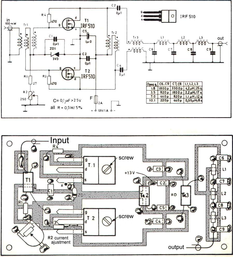


Ampli HF bandes basses bon marché...
Some good low power transistor transmitter links:
Grenade Radio
2003 marks the 10th year of the Grenade radio. The first Grenade was built in Texas USA
from surplus and bought parts, early in 1993.
The Grenade Project
The infamous Grenade Transmitter is being 'decoded' - the work in progress is here
Free Shortwave!
Another experimenter is attempting to homebrew a shortwave transmitter
to broadcast in AM mode; ncludes updates on progress
5 Watt (QRP Gallon) Power Amplifier
Low Budget 1 Watt Shortwave Transmitter
Two-stage transistor design will broadcast in AM mode
PCS Electronics
Marko has now introduced the AM MAX II transmitter,
a 10-watt unit with many nice features which also include PLL.
One version covers the longwave and mediumwave broadcast bands;
another version operates on shortwave and might be of interest to
ham radio operators who want to experiment with good old amplitude modulation.
(This is a good alternative to The Grenade Transmitter but beware of the Bugs into it!!)
SSTran
After observing the poor quality of the other kits on the market,
the operator of this company spent a couple of years intensely studying
low-power AM transmitter design and created the AMT3000.
Its features include PLL frequency synthesis, an audio compressor-limiter,
and a tunable antenna matching circuit that efficiently matches the rig's output
to short antennas without the need for additional loading coils.
Radio Morningstar Schematics Page
Most are in Dutch, but there's tons here, for many bands.
Harry's Homebrew Homepages
Amazing selection of well-written schematics for a wide variety of broadcasting gear
Radio QRP
Doggedly working to assemble a shortwave transmitter based
on The Animal's infamous "Grenade" design; has progress reports
The Famous Grenade Transmitter
The forum specially for the Grenade transmitter the modifications and discussion how to get it better
AM Stereo Exciter
Wenzel's transmitter
Bowden's transmitter
NCR AM88 kit
7 Watt Prototype
1 Watt Shortwaver (Español)
SM0VPO's Morse/AM transmitter
Quest's transmitter
The "Talking" Pixie 2 QRPp AM Transmitter
Micro Power AM Broadcast Transmitter
Here are some other QRP projects:
http://www.qsl.net/kd7rem/irf510ds.htm
http://cs.okanagan.bc.ca/ve7ouc/eng/kc6wdk-mirror/transmitter.html
http://www.qsl.net/al7fs/AL7FS2.html
http://www.qsl.net/k5lxp/projects/QRPTX/QRPTX.html
http://www.qsl.net/qrp/tx/317-tx.htm
http://www.qsl.net/qrp/tx/vu2vwn.htm
http://w1.859.telia.com/~u85920178/tx/hf-osc1.htm
http://w1.859.telia.com/~u85920178/tx/5watttx.htm
http://www.madisoncounty.net/~kj5tf/n7ksb.html
http://www.fix.net/~jparker/norcal/miniboots/miniboot.htm
http://www.qsl.net/k4msw/rigs.html
http://www.radiohc.org/Distributions/Dxers/ultra-simple-transmitter.html
http://www.qsl.net/qrp/tx.htm
http://www.pirateradio.us
http://worldwidedirt.tripod.com/gproject.html
http://www.angelfire.com/bc/radio/index.html
http://1watt-am.port5.com/
http://www.angelfire.com/de/RadioAnarchy/
http://www.usinternet.com/users/kyledrake/schematic/
http://homepage.eircom.net/~ei9gq/homebrew.html
http://members.home.nl/radiomorningstar/
http://www.mines.uidaho.edu/~keng/sch/
http://www.flashwebhost.com/circuit/index.php
http://www.part15.org/mwa/tech/tech.html
Give the Magnetic Loop Antenna a try:
http://www.antennex.com/preview/myloop.htm
http://www.g3ycc.karoo.net/loop.htm
http://www.qsl.net/mnqrp/Loop/Mag_Loops.htm
http://www.alphalink.com.au/~parkerp/nodec97.htm
http://www.qsl.net/pa3hbb/magloop2.htm
http://www.funklab.de/mloop.html
http://www.s-line.de/homepages/dl4sz/magloop.html
http://www.iri.tudelft.nl/~geurink/magnloop.htm
http://www.rys.nl/mat-div.htm
http://ftp.castel.nl/~levee01/antennaSome other good amateur QRP links
The "Tiny Tornado" QRPp Transceiver
Tiny Tornado Prototype by KA8MAV
Tiny Tornado Limited Edition Kits
Tiny-Tornado built by KC5WA
Tiny-Tornado built by AF8X
Tiny-Tornado built by N9IK
Tiny-Tornado built by N5ESEThe Micro-80
The Micro-80 by Oleg Borodin - RV3GMSmall Wonder Labs "Rock Mite"
QRPp-I Rock-Mite Pages
Small Wonder Labs
Rocky Mountain Rock-mite by N0RC
The "Rock-Mite" Files by N0RC"Pixie 2"
Elmer 001 - The Pixie 2 Project
QRPp-I Pixie Information Project (PIP)
Building a Pixie 2 by KA8MAV
QRPp-I Pixie 2 QRPp CW Transceiver Pages
HSC Electronic Supply (Pixie 2 Kit $9.95)
Kenneke Communications (Pixie 2 Kit $25.00)
The $10 Transceiver "Pixie 2" - JA9MAT
My Radio "PIXIE2" - JJ1SLW (English)
My Radio "PIXIE2" - JJ1SLW (Japanese)
The "Talking" Pixie 2 QRPp AM Transmitter
QRP Transceiver for less than $10 - AL7FS
The W1FB Pixie Transceiver
The HSC "PIXIE" 7040kc QRPp CW Transceiver - WA6BOY
QRPP Pixie - DF2OU
Mark Arvidson's Pixie 2 Page
Pixie Page - WA6OTP
Pixie 2 Tips Part 1 - WE6W
Pixie 2 Tips Part 2 - WE6W
Pixie 2 Resources by WE6W
The Great Dayton Building Contest 1995 - The Original Text
Pixie 2 Original Schematic
Pixie 2 Suggestions - WD8AAU
Pixie 2 (modified) board layout by WD8AAU
40 Meter (7.040+/-) PIXIE Page - AE4GX
1999 QRP To The Field day Pictures
Pixie 2 by WB8RCR
Dixie Pixie - WA4CHQ
20 Meter Pixie by KX7L
The Pixie 2 Transceiver - G3LHJ's Version
Der Pixie-TransceiverKnightLites "KnightSMiTe"
KnightSMiTe QRPp CW Transceiver (SOLD OUT)
QRP Transceiver for less than $10 - AL7FS
SMiTe - Der SMD-Pixie 2 (QRP)NorCal's "SMK-1"
NorCal's SMK-1 (SOLD OUT)
NorCal's SMK-1
NJ-QRP SMK-1 Enclosure Kit
The SMK-1 Easy One Watt+ Mod
SMK-1 Photos and More - WB8RCR
NorCal SMK-1 Photos on the Red Hot Radio Site
eHam.net Review
N5FC's Version of the NorCal SMK-1 KitNorCal's "38 Special"
NorCal's "38 Special"
The 38 SpecialNorCal's 49er
NorCal's "49er" (SOLD OUT)
The Mighty Arkansas 49er
49er Boards at Far CircuitsTIXIE
TIXIE Circuit Board from Far Circuits
QRP Transceiver for less than $10 - AL7FSDWM Communications "Peanut Whistle Two"
"Peanut Whistle Two" 40 Meter QRP CW TransmitterTuna Tin 2 (TT2/MRX)
NorCal's Back to the Future Project - The Tuna Tin 2
The Tuna Tin Two Gallery
N4UY's Tuna Tin II QRPp Rig
K0KP's Tuna Tin 2Atlanticon "Snap" Transceiver
The Atlanticon Kit: it's a "Snap"!FOXX-3 Transceiver
The FOXX-3 Transceiver (Kanga U.S.)
The FOXX-3 Transceiver (Kanga U.K.)
FOXX3 Construction Pictures
The Foxx-3 Mini Transceiver - AA3SJ
The FOXX3 - G3CWI
The "Mint Box Challenge" - G3CWI
FOXX-3 Built by W4JBMMicromountaineer
The Micromountaineer Revisited
Micromountaineers, Old (1973) and New (2000)Jersey FIREBALL 40 (revision A and B)
Jersey FIREBALL 40 (SOLD OUT)
Jersey Fireball 40 Built by WB8RCRSmall Wonder Labs
SW+ Series
Elmer 101 and Low-Cost QRP Tranceivers
Elmer101 Discussion of the SW40+ CW Transceiver
SW Series Stuff
SW Series "More Power"
Elmer 101 Information 7/31/98
A dictionary of SW-40+ components
K7QO's SW-30+ Page - Building the Kit Step-by-Step (AWESOME!)
KB1DXC Elmer 101 Page - SW-40+
Elmer 101 - Winter 2001
Wilderness Radio SSTOther
G3PTO Homebuilt Amateur Radios
QRP, QRPp and microwatting
K3WWP's Ham Radio Activities
He he ...! This smart guy made his "own" pirate-clone of the original website.
You can see the result here: Zelf een kortegolf zender bouwen?? Kijk Hier
But we still think the original website is better!
Here are a collection of books for the QRP HomeBrewer:
ARRL's Low Power Communication
-- The Art and Science of QRP by Richard Arland, K7SZ.
The low power game is one of ham radio's most exciting and rewarding challenges. Here's the lowdown on low power operating, from selecting gear, to advanced operating techniques, antennas, emergency communications, solar power, and more!
208 pages. © 1999, The American Radio Relay League. (ISBN: 0-87259-733-4) #7334 -- $14.95
Stealth Amateur Radio
-- Operate From Anywhere by Kirk A. Kleinschmidt, NT0Z.
Adventure into the world of hidden stations and invisible antennas! Set up and operate a station without calling attention to yourself. Successfully operate a low power (QRP) station. Install safe antennas, including indoor antennas. Build invisible antennas. Install and operate a mobile station, to "get away" from radio-forbidden locations. Operate a portable station from a campground, motel room, picnic area, mountaintop or other location. Handle interference from your station to nearby consumer electronics devices as well as to your station from other nearby devices. Use this book and enjoy operating from just about anywhere!
First edition, second printing, 2001. © 1999-2001, The American Radio Relay League, Inc. (ISBN: 0-87259-757-1) #7571 -- $14.95
Low Power Scrapbook
-- Hundreds of the very best projects from the G-QRP Club's magazine Sprat are brought together in this handy book. Includes low power transmitters, simple receivers, accessories, circuit and construction hints and antennas. Ideal for the experimenter or someone who likes the fun of building and operating their own radio equipment.
320 pages. © 2001, published by the Radio Society of Great Britain (RSGB). (ISBN: 1-872309-73-9) #LPSB -- $19.95
QRP Power
-- Whether you've just been bitten by the urge to operate flea power, or you've already discovered just how much fun it is to operate with 5 W or less, QRP Power is just what you've been looking for. It's crammed with projects you can build and resource information you can use. In addition to the best recent QRP-related articles from QST, QEX and The ARRL Handbook, there's a new, in-depth article on NN1G's popular 40-40 transceiver.
208 pages. First edition, © 1996, The American Radio Relay League, Inc. (ISBN: 0-87259-561-7) #5617 -- $12.00
W1FB's QRP Notebook
-- by Doug DeMaw, W1FB.
Packed with construction projects for QRP transmitters, receivers and accessories. This second edition is the completely rewritten successor to Doug's popular QRP Notebook, and features totally new circuits. Learn the inside secrets from this veteran builder, writer and former QST Technical Editor. Most of the projects feature printed circuit boards that are available from a commercial source. Gain understanding of circuits. Experience firsthand the thrill of making contacts using equipment that you built.
184 pages. Second edition, third printing 1999, © 1991-1999, The American Radio Relay League, Inc. (ISBN: 0-87259-365-7) #3657 -- $10.00
QRP Basics
-- by Rev. George Dobbs, G3RJV
Do you want a new challenge? Have you ever wanted to try QRP (using 5 watts and less)? Do you want to improve your QRP station? Do you want to build a working transmitter or receiver? This book will help you do all of these things.
"QRP Basics" tells of the fun to be had by operating with low power, both from home and in the great outdoors. Advice is given on how to get the best results from a QRP station, and how to try out QRP if you haven't before. A large range of commercial QRP equipment and kits are described. Much of the book explains how to construct your own station, including complete transmitters and receivers, and accessories. Even the experienced constructor will appreciate the sections on toroidal coils, construction techniques and equipping a workshop. Finally, there are lists of contests, awards, books and organizations of interest to the QRP operator.
"QRP Basics" will enrich your enjoyment of Amateur Radio. It will inspire you to start building. It may even get you out in the open air. Explore the fun!
208 pages. © 2003, by Radio Society of Great Britain (RSGB).
(ISBN: 1-872309-91-7) #9031 -- $26.00
The Electronics of Radio
-- by David B. Rutledge, KN6EK
An introduction to analog electronics in the context of radio, and through the design and construction of a radio transceiver (the NorCal 40A QRP rig). A structured (college-level) approach describes basic electronic components and simple circuits, filters, amplifiers, oscillators, mixers, and antennas. Includes circuit simulation software (diskette), Puff.
431 pages. First edition, © 1999. Published by Cambridge University Press. (ISBN: 0-521-64645-6) #ERAD -- $44.95
The Low Frequency Experimenter’s Handbook
-- by Peter Dodd, G3LDO
Written to meet the needs of amateurs and experimenters who have an interest in low power radio techniques below 200 kHz. Most of the techniques described are targeted at those using the 136 kHz band, but they are also of great interest to readers in New Zealand and Australia with the 183 kHz band and the Lowfers in the USA on 180 kHz.
The bulk of the material in the book comprises contributions from experimenters world wide and covers antennas, propagation, transmitters, special modes and test equipment, and discusses some applications such as communication with caving enthusiasts.
All those interested in exploring the new frontier of the LF bands will welcome this invaluable and unique reference, whether they tend to transmitting or are content just to receive.
112 pages. © 2000. Published by the Radio Society of Great Britain (RSGB). (ISBN: 1-872309-65-8) #RLFS -- $32.00
|
Updated 2005-11-20
Solar X-rays: Geomagnetic Field: |
  |
PIRATE RADIO EXPLOSION
By Pat MurphyNever in recent history have there been so many unlicensed or pirate broadcasters on the H.F. bands as there are now. Its a fact supported by checking the logs of veteran pirate DX'ers who send those logs to the ACE, NASWA, Pirate Pages and of course the Pirates Den. During the late 1980's one could spend months waiting for a pirate broadcast and never hear anything,except static. You need only tune into 6955khz in AM or SSB on any weekend day or night and you can hear any number of different pirate radio broadcasts. As a shortwave listener who has spent a lot of time chasing pirate broadcasts for over a decade, I can tell you, it has been a pleasant surprise in the last year to hear so many new and innovative broadcasters take to the airwaves. On can't help but wonder, WHY?
The real question is: "What the heck is going on???"
There are several factors responsible for this explosion of unlicensed and pirate radio transmissions in the past year. First and foremost is the Federal Government downsizing within the Commerce Department. The F.C.C. falls under the jurisdiction of the Department of Commerce and has not only had staff and budget cuts, but has had its priorities redirected by Congress. The Telecommunications Bill of 1996 has Washington bureaucrats scrambling to deal with the onslaught of technologies at much higher frequencies than the antiquated H.F. bands. F.C.C. Field offices closed down all over the country in June of this year and complaints of interference are being handled by a toll free number that is answered in the Laurel, Maryland monitoring station. But don't expect a speedy dispatch of Federal Agents to a plea of "Help" from interference. The F.C.C. has adopted the policy of "The blame for interference on the person receiving the interference." The F.C.C. bulletin CIB-10 goes on to state that most interference "is caused by the design or construction of the Consumer Electronic product and not by the radio operator, or is a technical problem, not a law enforcement problem." CIB-10 then invites consumers to file a complaint, with the manufacturer, not the F.C.C. In fact, during a recent call to the FCC Gettysburg, PA. office, we were greeted by a recording that gave menu options, of which included, "interference to phones or home appliances." After punching the appropriate button we were told that "interference calls should be directed to the manufacturer" and that the FCC was not going to pursue these complaints any further. This is all adding additional pressure to the regulatory body plus there is a plan in front of Congress that would move the office of the F.C.C. to the Executive Branch (under the White House) and reduce the staff to 250 people. Keep in mind this plan has not been acted upon but is still being considered and if it were to be implemented, would be an additional factor that would encourage the Free Radio enthusiast to practice their on air craft.
Another and significant fact is the innovative technology of pirate broadcasters in developing new and smaller portable transmitters. Over the past year we had a virtual "gold rush" to the airwaves as a direct result of this kind of technology. Developed by veteran pirate broadcaster the "Radio Animal", is a 10-watt, AM, Crystal Controlled "Grenade" transmitter. "Animal" told me in a recent interview that "the grenade transmitter has been the product of a long process over a lot of years of pirate broadcasting. I wanted a transmitter that was small, portable and solid state. Pirates were using technology from the 50's and 60's, stuff they'd find used at hamfests. I wanted to use modern technology for the high tech receivers that listeners are using." The Radio Animal had his detractors when he first tried this new type of transmitter. He said; "What's so funny is that when I developed the 10-watt Grenade, people told me that no one would hear it." Its interesting to note that in the most recent "Pirate Radio Directory 8th Edition" (Tiare publications) out of the top 5 stations with the most heard transmissions, 4 of them use Animals Grenade 10-watt transmitter. Animal told me, "I just wanted to contribute to the pirate scene to make it better." There is no question he has accomplished his goal and revolutionized pirate radio.
Paul Art of "Voice of the Rock" said, "you can haul this unit, which weighs next to nothing out on a raft, to an Island with some batteries and a tape recorder and be heard for thousands of miles and be virtually unreachable by F.C.C Agents, who aren't going to hunt for an Island to find the operator." Not to mention the fact, that by the time the F.C.C. could dispatch someone, the transmissions would have been long over and done with, and the pirate broadcaster leaving no trace.
Stations using the "Grenade" are reporting that DX'ers are hearing them all across North America and are being heard in England, Germany and Scotland. In recent reports to WREC Radio Free East Coast, P.J. Spanks says, "I've received reception reports from England and Scotland using the 10-watt Grenade." Sparx also points out that the "Audio circuitry is fabulous, and its hard to send a bad signal." Radio Free Speech's, Bill 0. Rights got reports from Canada, USA, Germany and Scotland for a May broadcast with the same unit. In fact, the only transmitter that Rights has used over the past year has been the "Grenade" transmitter. Pirate Pete at WRV, the Radio Virus says, "the Grenade makes it possible to have 5 or 6 different transmitter locations because all I have to do is hike into the woods, hook up the antenna and a battery pack and we're On the Air." NAPRS, the North American Pirate Relay Service has had similar success with their "Grenade" as has Animals own station, WKND, when he did a marathon from the woods with the signal being heard all over North America. In interviewing the station operators, its obvious they are more than happy with the results of this little power house transmitter that allows them mobility and some degree of anonymity by being away from homes, buildings and people. Hams have long known they can reach long distances using the low power QRP transmitters using CW, but thousands of miles using 10-watts in the AM mode is unheard of in these modern times of 5OOkw shortwave transmitters. Since doing a "Pirate Broadcast" is illegal, it appears the pirates have employed this new technology to go mobile with their activities and in the true pirate spirit, taken advantage of a financial and dis-organizational problem with their real or imagined oppressors. This has made listening to pirates not only easier for the DX'er but the selection of stations formats far more diverse.
Here is the set up of Radio Free Speech. Station Manager Bill 0. Rights calls this his "station in a suitcase" Transmitter, tape recorder for pre-recorded shows, power cords, power supply, plug in crystals and H.F. Dipole with Coax all rolled up into on little package. Rights says, "I've set up on the tops of mountains in National Parks where we threw up the dipole in a tree and would do a broadcast and be gone, all in 35-minutes." "It takes maybe 10-minutes to set it up and two minutes to take down. I love it." Pirate Pete at WRV agrees, "Its allowed us a pirate operators to be a lot harder to locate. In fact, I've got numerous sites for my set up. Now you see us, Now you don't."
So at least two significant factors that have contributed to the explosion of pirate broadcasts on the H.F. bands in the last year, have been the compact technology of transmitters, like the "Grenade" and the FCC Downsizing and reduction of staff. It has made the past year one of the most active and fascinating for those of us who spend our weekends searching the airwaves for what used to be elusive signals that we affectionately call "Pirate" radio broadcasts. So all you people who have said, "I can never hear a pirate when I tune into, now is the time to try again. If you can't hear one now, you need a new radio, antenna or both. Only time will tell where this trend takes us, but one thing is for sure, this is an interesting and exciting time for DX'ers chasing pirate signals. Good DX to you!
Pat Murphy - Deep in the Dismal Swamps of Virginia
HOMELAND SECURITY
Field Day, Expedient Antennas, And QRP
by Rich Arland, K7SZObservant readers of this column will realize that I have a long-standing commitment to Emergency Communications (EmComm), training, and QRP (under 5-watt ham radio). Without a doubt, QRP and EmComm are NOT mutually exclusive terms. There is only a 13-dB (approximately 2.5-S-unit) difference between a 100-watt and a 5-watt signal over identical HF circuit paths. Add the American Radio Relay League’s annual Field Day exercise into the mix, and you have a perfect opportunity to get out of the shack, hit the bush, and play radio. The ultimate goal, of course, is to test your EmComm skills, your “coping skills,” do some outside-the-box thinking, and improve your ability to provide emergency communications in a field environment using expedient stations and antennas.
QRP provides a small, but growing, faction of radio amateurs the opportunity to use ultra-small, extremely portable radio gear, much of which can be built from scratch or kits, to provide communications on a worldwide scale. Antennas range from simple dipole antennas erected in the trees to beams on towers, and literally everything in between. QRP and antenna experimentation go hand in hand, as does the kit/scratch building of gear.
It’s one thing to plan and participate in emergency training exercises but it’s quite another to be involved in an actual emergency with little or no warning. Typically in emergency disaster training scenarios, there is a “ramp-up” time and everyone knows when and where the exercise will take place, where they’re supposed to report, and what their basic duties are. Things go smoothly thanks to this “anticipatory thinking.”
In the real world, however, seldom are we accorded any “ramp-up” time. All too often we (I am using the collective “we” as in all of us emergency communicators) are thrust into a situation with little or no warning. There is only time to react, and our initial reactions must be correct if we are to be useful during an emergency.In the various military and civilian survival manuals I have in my library, it is stressed that the first few things you do, your initial reactions, to the emergency/disaster can mean the difference between life and death for you and your party. Knowing what to do and taking the time to think things through will enable you and your party to survive, whether we’re talking about responding to a communications emergency or finding shelter during a tornado or earthquake, or reacting to terrorist actions like the events of 9/11. Confidence in your own abilities plus appropriate training, coupled with your ability to critically analyze a rapidly changing situation and to react properly to this dangerous situation (or multiple situations), will be your best weapons against terrorism and/or natural/man-made disasters.
-----------------------------------------------------------------------------------
Special thanks to Pigmeat Martin, VOAB
QRP PROJECTS, KITS
- 7N3WVM QRP, Construction, and others
- GW0TQM QRP, antennas, software
- QRP kitts, pant and stuff - KI7MN
- QRP Antennas WB2VUO
- QRP Antenna tuner N3WVM
- JF1OZL QRP Construction -bilingual: japanese-english
- KL7JAF Proyects QRP
- Radio Construction Projects from GQRP
- QRP Proyects HF Corner-QRP
- QRP Antenna 5 band 2 elem.
- QRP projects
- Great wire antenna QRP
- A2 Elem. BOBtail Curtain - Antenna QRP
- 2 Meters CW transmiter by NH6IL
- 15 Meters QRP transmitter by NH6IL
- 20 Meters QRP transmitter by NH6IL
- 40 Maters QRP transmitter by NH6IL
- 80 Meters QRP transmitter by NH6IL
- Another 80 Meters QRP transmitter by NH6IL
- 80 Meters QRP CW project 3 by NH6IL
- 80 Meters QRP CW (low parts) by NH6IL
- 80 Meters QRP CW transmitter and VFO by NH6IL
- 160 Meters QRP AM transmitter by NH6IL
- 15 Watts on 80/40 Meter transmitter by NH6IL
- BFO Synthesizer by NH6IL
- Long-Wire Antenna Coupler
- TSB transmitter by NH6IL
- Kanga Kits
- Kanga USA - kits for the amateur
- Balloon Project Home
- Radio Devices Co. QRP Kits, BA books etc.
- S & S Engineering - QRP kits and accessories.
- QRP KJ5VW antennas, software
- GW0TQM QRP, antennas, software
- Northern California QRP Club. Projects QRP -Links-
- QRP kitts, pant and stuff - KI7MN
- QRP project GM0RWU
- QRP World -Software, Projects, Links-
- QRP Antenna 5 band 2 elem.
- Great wire antenna QRP
- A2 Elem. BOBtail Curtain - Antenna QRP
- Equipment QRP Catalog
- QRP Transceiver W1CER and W1NPG by july 1973 QST [ Page 2 ] [ Page 3 ] [ Page 4 ] [ Page 5 ] [ Page 6 ] [ Page 7 ]
- QRP Wilderness Radio KC-1 keyer/frequency counter
- QRP Wilderness Radio Serra multiband cw transceiver
- QRP Ten Ten Argo 556 ssb/cw transceiver
- Oak Hills Research WM-1 QRP wattmeter
- QRP Oak Hills Research Explorer II
- 160-10 meters QRP CW transceiver
- LDG AT-QRP Auto Tunner
- Nor Cal circuit board
- QRP CW by K5FO
- Keys, Bugs, and Paddles
- QRP Hints and Kinks
- QRP Pixie Transceiver
- QRP Wilderness Radio SST photos
- Envirotronic Paddle
- Internet Code Course K5FO
- QRP 49er 40 m CW Transceiver Kit
- QRP 38 Special - 30 M Transceiver kit
- SP-750 40 M CW Transceiver kit
- The Schematic of Regenerative OV2 Receiver by JA9MAT
- QRP The Schematic of Regenerative OV1 Receiver by JA9MAT
- QRP list of kits and componnents by UK
- QRP recommended books by RSGB
- QRP 38 links by projects Antenna topics
- Hints and Tips
- QRP Projects by KE4ARM by 160-80-40-20-15 and 2 meters
- QRP Reviews -antennas, transceivers, AT-
- Weskit BN-1 Tx/Rx using one 3A5 dual triode by KC0CW
- Harry's 7 watt all band EL95 tube transmitter, by SM0VPO
- 10 MHZ 2N3553 QRP transmiter by VE3DNL
- Small 2-tube cigar box QRP transmitter
- QRP 5 watt transmitter 6T9 tube -excellent- Page 1 [ Page 2 ] [ Page 3 ] [ Page 4 ]
- 6V6-6L6 Transmitter, project 1947
- Cake Pan CW-5 tube transmitter kit
- C.M. Howes - Fine British QRP Kits
- 6AQ5A QRP 80/40 meters transmitter AA0HU
- 6BM8 Transmitter by PA3GNR
- Projects, Circuits, Hints and Kinks from the Minnesota QRP Society
- HOMEBREW QRP IS GUD 4 U
- QRP World - Welcome
- New Jersey QRP Club
- QRP Amateur Radio Club International (QRP ARCI) (RTPnet)
- QRP WORLD
- QRP Periodicals
- QRP-L
- The NorCal Page
- Internet QRP Club Information
- QRP-L Archive by thread
- Amateur Radio QRP Pages
- IT9XXS QRP Pages
- Directory of /pub/radio/ham/qrp
- Directory of /pub/listserv/qrp-l
- QRP Plus Transceiver_MODS1-Receiver Modifications
- QRP Plus Transceiver MODS2-Transmitter Modifications
- QRP Plus Transceiver MODS3-Notes and Corrections
- QRP Plus Transceiver MODS4-Fixing "Chirp"
- QRP Plus Transceiver MODS5-Temperature Stabilization
- More mods for the QRP Plus (reprint from Winter 2003 QRP Quarterly)
- Samlex Power Supply_Mods
- Cleaner Keying for the Ten-Tec 509
- Curing VHF Interference in Ten-Tec Argonauts
- Improving SSB Performance of the Ten-Tec Argonaut 509
- Norcal 20 modifications/improvements
- Improvements for the W9GR DSP Audio Filter
- "Peak Power" Modification for the WM-1 QRP Wattmeter
- QPR Cub - Mod. 1 - Improved Linearity of Tuning
- QRP Cub - Mod. 2 - Improved sidetone level, QSK, envelope
- QRP Cub - Mod. 3 - Reduced Warm Up Drift
- QRP Cub - RIT Mod by Larry East, W1HUE
- QRP Cub - QSK Mod provided by Cub Designer Rick Littlefield, K1BQT
- AT11MP Automatic ATU with cross meter readout
- DX/50/70 VHF Transverter
- RT11 Remote mounted Auto ATU
- RX1 Receiver
- Z11 ATU QRP Low Current ATU
- AMP1 20 Watt Low Drive HF Linear Amplifier
- AMP3 4 Watt 50 MHz Linear Amplifier with Low Pass Filter
- AMP5 /30 /50 /70 6-9 Watt BJT Linear Amplifier with Low Pass Filter
- AMP6 30-70 MHz BJT Low Drive Linear Amplifier
- DDS3 A Direct Digital Synthesiser with Display
- LPF109 Multiband LPF with Stockton Bridge
- PL9 9 Band Phase Lock Loop
- RF/50/70 Transceiver Front End
- RTX-LPF Monoband HF Low Pass Filter with Relay Antenna Change Over
- PRA9 High Dynamic Range Receiver Pre-Amplifier
- VFO55 Variable Frequency Oscillator with RIT
- QRPp International Radio Club's CW & Morse Code Pages
- "So You Want To Learn Morse Code" By David G. Finley, N1IRZ
- "Your Novice Accent And What To Do About It" By Keith S. Williams, W6DTY
- N9BOR Morse Code Links
- AI2G's 6L6 Xmtr Schematic WB7AWK
- HSC Electronic Supply
- HSC Electronic Supply (Pixie 2 Kit)
- Kanga U.S. Kits
- The FOXX-3 Transceiver (Kanga U.S.)
- The FOXX-3 Transceiver (Kanga U.K.)
- Jersey FIREBALL 40 (SOLD OUT)
- KnightLites KnightSMiTe QRPp CW Transceiver (SOLD OUT)
- Lectrokit Spider
- "Peanut Whistle Two" 40 Meter QRP CW Transmitter
- Small Wonder Labs
- NorCal's SMK-1 (SOLD OUT)
- NorCal's Back to the Future Project - The Tuna Tin 2
- Emtech NW Kits
- Ten Tec QRP Kits
- Wilderness Radio
- Allied Electronics
- Carl's Kits
- Custom Enclosures by KE6RIE
- Dan's Small Parts
- Embedded Research
- Far Circuits
- G3TUX (Howes Kits and Other Kits)
- Hands Electronics (U.K.)
- Hands Electronics (U.S.)
- HB Electronics (variable caps and more)
- KD1JV "Melt Solder" QRP Kits
- KD7S homemade enclosure instructions (Elmer 101)
- KK7B Kits
- KL7JAF projects (Broken Link - 11/25/2001)
- KnightLites
- KU4QO's SW40+ Elmer 101 Project
- MFJ Enterprises, Inc.
- NW QRP Club
- Nor-Cal QRP Club
- Nor-Cal Suppliers List
- QRP Kit Comparison Page (Broken Link 09/06/2001)
- PacTec Enclosures
- Radio Adventures Company (specialty IC's and more!)
- RF Parts Company
- SESCOM Aluminum Enclosures
- Ten Tec
- The Toroid King - Kits and Parts (Over 25,000 Toroids IN STOCK!)
- WA6OTP - Permeability Tuned Oscillator (PTO)
- The R.F. Connection - Coax Cable and Connectors
- Bekaert ECD Solar Systems
- Photovoltaic Power Corp.
- Solar Direct - Uni-Solar Panels
- QRP Project Amateur Radio Berlín
- Digital QRP Breadboard Project
- KD1JV Kits
Kits
all electronics
almost all digital
american qrp club
antique electronic
centerpointe
circuit specialists
debco electronic kits
dwm enterprises
elecraft
electronics-usa(whiterook)
embedded research
emtech
gateway
gibson tech
glowbugkits.com
hallbar electronics
hobbytron
jackson harbor
kanga us
kanga uk
k series keyers (k1el)
ldg electronics
mpja electronics
noga (amazing little kits!)
norcal
oak hills research
qkits
radio adventures
rainbow kits
ramsey electronics
red hot radio
rf parts
science workshop
small wonder labs
s & s engineering
ten-tec
vectronics, inc.
Velleman
wilderness radioRECEIVERS & TRANSMITERS BY QRP ARCI PROJECTS:
- W5JH Regen Project
- W8EDU's Big List
- R2T2 Haven - K0JD
- 21 Mhz Rig from JF1OZL
- Radio Receiver Site
- G3YCC Project Page
- KD7S Idea Pages
- 7N3WVM's Design site
- N5FC's Great Circuits
Other nice Projects
- North Georgia Club Projects including the NoGaPiG kit
- Tuna Tin II - Jake, N4UY
- The NorCal Tuna Tin 2
- K8IQY's 2N2/40 Rig
- NJ QRP Projects
- Alex S57NAN Projects
- VE7JPC's FB site
- EI9GQ Projects
- OK1DPX Projects
- ARRL QRP Projects
- HC908 Daughtercard
Science, Tech & Electronics Ed
- The Elmer 101 Project
- 101Science
- VK2TIP's Electronics Ed
- Scot's Guide to Electronics
- QRP Homebuilder
- Kitchin Regen Rcvr Educational Project
- New Zealand Rcvr
- Electronic Component Database
- Heathkit Schematics
Links-Technical Pubs & Tech Data
- Here is a list of technical magazines from Idea Exchange - Jan. 2000 issue of QQ. Also, included are links to each.
- Electronic Construction Techniques - N1FN's got it!
- Parts Links- from W1HUE
- Links - Semiconductor DATA- ChipDir or ChipInfo
Pixie - world's simplest rig?
- Where to get a kit?
- Dixie Pixie
- Please check out very nice Pixie JA9MAT
- QRPp International
- WE6W's Pixie List
- AL7FS's Great page
KANGA PRODUCTS:
- The ONER Transmitter
- The OXO Transmitters
- The JBS Transmitter
- Add-On Amplifier
- Novice DIY Amplifier
- Audio "S" Meter
- The Sudden Receiver
- The New Sudden-2 Receiver
- The FOXX-3 Transceiver
- TiCK-1 Iambic Keyer
- TiCK-4 Iambic Keyer
- CMOS Iambic Keyer
- Morse Practice Oscillator
- RF-Actuated Sidetone
- The New Low-Pass Filter
- Dummy Antenna
- The Crystal Marker
- Sandford Wattmeter
- Stockton Wattmeter
- Simple T/R Changeover
- RF T/R Changeover
QRP ACCESSORIES:
- Mini-Keys, Mini-Paddles, Mini-keyers, and QRP accessories
- The Art of Soldering book
- The QRP Component Company G3TUX
- Bowood Electronics Ltd.
- Sycom
- Byers Chassis Kits
- Emtech ZM-2 QRP Antenna Tuner
- NJ-QRP Rainbow Tuner & SWR Bridge
- Bomar Crystals
- International Crystal Manufacturing Co., Inc.
- MH Electronics
- NorCal QRP Club
- Ocean State Electronics
- Almost All Digital Electronics
- Az ScQRPions Stinger Singer
- Oak Hills Labs
- Small Wonder Labs 'FREQ-Mite'
- Wilderness Radio Kc1 Keyer/Counter
- Permeability Tuned Oscillator (PTO) by WA6OTP
- Kanga U.S. - ONER VFO, etc.
- DVFO-II --- Digital VFO With DDS
- S&S Engineering Digital Displays
- Embedded Research - TiCK Keyers
- Jackson Harbor Press (PK-3 Keyer Chips and Kits)
- K1EL - Home of the K-keyer Chips and Kits
- The Vibroplex Company, Inc.
- Whiterook Products - miniature keys & paddles
- Bencher, Inc.
- G4ZPY Morse Keys - Micro Miniature Pump Key
- Morse Express
- HSC Electronic Supply
- HSC Electronic Supply (Pixie 2 Kit)
- Kanga U.S. Kits
- The FOXX-3 Transceiver (Kanga U.S.)
- The FOXX-3 Transceiver (Kanga U.K.)
- Jersey FIREBALL 40 (SOLD OUT)
- KnightLites KnightSMiTe QRPp CW Transceiver (SOLD OUT)
- Lectrokit Spider
- "Peanut Whistle Two" 40 Meter QRP CW Transmitter
- Small Wonder Labs
- NorCal's SMK-1 (SOLD OUT)
- NorCal's Back to the Future Project - The Tuna Tin 2
- Emtech NW Kits
- Ten Tec QRP Kits
- Wilderness Radio
- Digi-Key
- Mouser Electronics
- Jameco
- FAR Circuits
- Radio Shack
- Amidon
- ByteMark
- Motorola
- Texas Instruments
- Philips Semiconductors
- Fair Radio Sales
- Barker & Williamson
- International Crystal
- NTE Electronics
- Radio Adventures
- Vector Electronics
- Harbor Freight Tools
- Lashen Electronics
- DC Electronics
- Parts Express
- Unicorn Electronics
- All Electronics
- B.G.Micro
- Goldmine Electronics
supplies
- all electronics
- alltronics
- amidon inc
- barker & williamson
- bomar crystal
- byers chassis kits
- bytemark corp
- dahl amateur radio
- dan's small parts
- debco
- digikey corporation
- eis electronics
- electronix express
- extech instruments
- far circuits
- fair radio sales
- fairchild semi
- halted electronics
- international crystal
- jameco electronics
- K6LS test equipment
- the led light
- lashen electronics
- maxim
- mfj enterprises
- mh electronics
- milestone technologies
- mini-circuits
- mitchell electronics
- morse express
- mouser electronics
- national semi
- nte electronics
- ocean state electronics
- palm radio (key)
- patcomm
- radio adventures
- radioshack.com
- r.f. connection
- science & surplus
- stf electronics (pat bunn)
- vector electronic co.
- webtronics
- west coast magnetics
- xtal set society
HANDS ELECTRONICS:
- RT11 Remote mount Auto ATU
- AMP-100 100w Linear Amplifer
- Z11 QRP-ATU Automatic 10 Watt Antenna L Tuner
- RBA-1 4:1 Balun
KANGA COMPONENTS:
- Resistors
- Presets
- Capacitors
- Inductors
- Toroids
- Crystals
- Resonators
- Diodes
- Transistors
- ICs
- Connectors
- Meters
- Hardware
- PSK31
- Cable
QRP ANTENNAS, AT-TUNNER
- "A Balanced Balanced Antenna Tuner" - AG6K
- "L" Tuner Information
- W4RNL (LB Cebik) Antennas
- The Resistive SWR Bridge
- The Visual LED SWR Indicator Page
- Building a Pi-L Antenna Tuner
- The Z-Match Antenna Tuner
- Visual LED SWR Indicator
- HF ANTENNA TUNER by Harry Lythall - SM0VPO
- The Broomstick Special - "helically wound" wire antenna
- A Film-Can Transmatch
- A Bright Idea for Wrestling With SWR in the Field
- Helitrix - The Slinky that became an Antenna
- Helical Antenna Info
- Slinky Antenna References
The "Tiny Tornado" QRPp Transceiver
- "Tiny Tornado" Prototype by KA8MAV
- "Tiny Tornado" Limited Edition Kits
- Tiny-Tornado built by KC5WA
- Tiny-Tornado built by AF8X
- Tiny-Tornado built by N9IK
- Tiny-Tornado built by N5ESE
The Micro-80
Small Wonder Labs "Rock Mite"
- QRPp-I Rock-Mite Pages
- Small Wonder Labs
- Rocky Mountain Rock-mite by N0RC
- The "Rock-Mite" Files by N0RC
"Pixie 2"
- Elmer 001 - The Pixie 2 Project
- QRPp-I Pixie Information Project (PIP)
- Building a Pixie 2 by KA8MAV
- QRPp-I Pixie 2 QRPp CW Transceiver Pages
- HSC Electronic Supply (Pixie 2 Kit $9.95)
- Kenneke Communications (Pixie 2 Kit $25.00)
- The $10 Transceiver "Pixie 2" - JA9MAT
- My Radio "PIXIE2" - JJ1SLW (English)
- My Radio "PIXIE2" - JJ1SLW (Japanese)
- The "Talking" Pixie 2 QRPp AM Transmitter
- QRP Transceiver for less than $10 - AL7FS
- The W1FB Pixie Transceiver
- The HSC "PIXIE" 7040kc QRPp CW Transceiver - WA6BOY
- QRPP Pixie - DF2OU
- Mark Arvidson's Pixie 2 Page
- Pixie Page - WA6OTP
- Pixie 2 Tips Part 1 - WE6W
- Pixie 2 Tips Part 2 - WE6W
- Pixie 2 Resources by WE6W
- The Great Dayton Building Contest 1995 - The Original Text
- Pixie 2 Original Schematic
- Pixie 2 Suggestions - WD8AAU
- Pixie 2 (modified) board layout by WD8AAU
- 40 Meter (7.040+/-) PIXIE Page - AE4GX
- 1999 QRP To The Field day Pictures
- Pixie 2 by WB8RCR
- Dixie Pixie - WA4CHQ
- 20 Meter Pixie by KX7L
- The Pixie 2 Transceiver - G3LHJ's Version
- Der Pixie-Transceiver
KnightLites "KnightSMiTe"
- KnightSMiTe QRPp CW Transceiver (SOLD OUT)
- QRP Transceiver for less than $10 - AL7FS
- SMiTe - Der SMD-Pixie 2 (QRP)
NorCal's "SMK-1"
- NorCal's SMK-1 (SOLD OUT)
- NorCal's SMK-1
- NJ-QRP SMK-1 Enclosure Kit
- The SMK-1 Easy One Watt+ Mod
- SMK-1 Photos and More - WB8RCR
- NorCal SMK-1 Photos on the Red Hot Radio Site
- eHam.net Review
- N5FC's Version of the NorCal SMK-1 Kit
NorCal's "38 Special"
NorCal's 49er
TIXIE
DWM Communications "Peanut Whistle Two"
Tuna Tin 2 (TT2/MRX)
- NorCal's Back to the Future Project - The Tuna Tin 2
- The Tuna Tin Two Gallery
- N4UY's Tuna Tin II QRPp Rig
- K0KP's Tuna Tin 2
Atlanticon "Snap" Transceiver
FOXX-3 Transceiver
- The FOXX-3 Transceiver (Kanga U.S.)
- The FOXX-3 Transceiver (Kanga U.K.)
- FOXX3 Construction Pictures
- The Foxx-3 Mini Transceiver - AA3SJ
- The FOXX3 - G3CWI
- The "Mint Box Challenge" - G3CWI
- FOXX-3 Built by W4JBM
Micromountaineer
Jersey FIREBALL 40 (revision A and B)
Small Wonder Labs
- SW+ Series
- Elmer 101 and Low-Cost QRP Tranceivers
- Elmer101 Discussion of the SW40+ CW Transceiver
- SW Series Stuff
- SW Series "More Power"
- Elmer 101 Information 7/31/98
- A dictionary of SW-40+ components
- K7QO's SW-30+ Page - Building the Kit Step-by-Step (AWESOME!)
- KB1DXC Elmer 101 Page - SW-40+
- Elmer 101 - Winter 2001
Wilderness Radio SST
Other
QRP VENDORS
- Small Wonder Labs
- Red Hot Radio
- EleCraft
- Embedded Research
- EMTECH
- Kanga US
- Dan's Small Parts
- American Morse
- HB Electronics
- S&S Engineering
- Oak Hills Research
- Whiterook Products Co.
- Ten-Tec
- Wilderness Radio
- Jade Products
- Milestone Technologies
- DIY Electronics
- Almost All Digital Electronics
- Vectronics
- LDG Electronics
- Ramsey Electronics
- Hy Power Antennas
- MFJ Enterprises
- QRP Books
- Amateur Electronic Supply
QRP MAGAZINES:
- QRP-L
- QRP Homebrewer Magazine by NJ-QRP
- The ARS Sojourner
- W5WWW Links
- AntenneX Magazine
- Ham Encyclopedia
TECHNICAL AND THEORY QRP
- Adventure with Milliwatts - Worked All States
- KJ5TF QRP Milliwatt Information Page
- ARRLWeb: QRP -- What, Why and How
- Ian Purdie VK2TIP's Electronics Tutorials
- Electronics-Tutorials.com
- LC Filters Design
- Elmer 101 - Winter 2001
- Radio & Electronics School - Study Notes (.pdf)
- Elements of AC Electricity - Tutorials
- Smith Chart
- N9SSA Distance and MPW Calculator
- Distance and Bearing Calculator
- Recharging Batteries
- BatteryWeb.com Chargers
- Online AM Transmiter Harmonics Calculator
- Ian Purdie VK2TIP's Electronics Tutorials
- Electronics-Tutorials.com
- LC Filters Design
- Elmer 101 - Winter 2001
- Radio & Electronics School - Study Notes (.pdf)
- Elements of AC Electricity - Tutorials
- Smith Chart
- Almost All Digital Electronics (L/C Meter IIB)
- Autek Research - RF Analyzers
- Brown Aviation Tool Supply Company
- VE3DNL Marker Generator (Review)
- New England QRP Club - Noise Bridge Kit
Your QRP ARCI team is standing by to help you!
What is amateur radio? ARRL----NW7US Site
What is QRP? QRPAL7FS answers this question
Where is most of the QRP activity? Calling Frequencies or Calling Freqs - CW
Where can I find out more about building radios, transceivers? QRP Technical/Project Page QRP World
I'd like to find out if others enjoy taking their radios backpacking and to the field? Adventure Radio Society
Where do I get a very simple radio? Pixie
What about a little more performance? There are many kit manufacturers but check these: SWL.....EMtech.....Wilderness.....Red Hot Radio
What about antennas? Stealth Antennas .....L.B.Cebik's Famous Antenna Site
I'd like to see some personal experiences? K4EQ's Excitement Story
Where can I find more info on QRP? Quick Links
I'd like to submit an article or question for the QRP Quarterly! QQ Staff
Can you do QRP on satellites? WB6FZH's Hand Held Satellite Experience
My QRP operation in the '96 SS
Answering Readers Questions & Coments I
DXing with minimal QRP - Part 1
DXing with minimal QRP - Part 2
Review 1st year of columns + comments
VE3ZAA's Story + QRP & Cycle 23
Answering Readers Questions & Comments II
Answering Readers Questions & Comments III
Answering Readers Questions & Comments IV
Answering Readers Questions & Comments V
My New QRP(?) Rig $ Web Site Update
Answeing Readers Questions & Coments VI
DXing With Minimal QRP: Part 2
DXing With Minimal QRP: Part 3
Answering Readers Questions & Comments VII
Touring the HF Bands (and 160M)
The MRX-40 Mini Receiver (advanced) (163,840 bytes, PDF file) QST September 1997,
pp. 59-60 A tiny 40 meter amateur band Morse code receiver barely larger than a half dollar.Rescaling the MRX-40 Receiver for 80 Meters
QST May 2001, pp. 98-99
Feedback: Rescaling the MRX-40 Receiver for 80 Meters
QST Jul 2001, p. 31The NJQRP Squirt (151,957 bytes, PDF file) QST April 2001, pp. 40-43
A reduced-size 80-meter antenna designed for small lots, portable use,
and a fine companion for QRP or the Warbler PSK31 Transceiver .A Two-Transistor Transmitter for 30 meters (564,542 bytes, PDF file)
QST February 1984, pp. 46-47, Hints and KinksAn Optimized QRP Transceiver for 7 MHz (1,424,733 bytes, PDF file)
ARRL Handbook 1993, pp. 30-37 to 30-40 Here is a rig that provides a real challenge
for the QRP home builder. Nonetheless, this is a classic circuit and a favorite in the QRP community.A QRP SSB/CW Transceiver for 14MHz -- Part 1 (682,742 bytes, PDF file)
QST December 1989, pp. 18-21 Exotic circuitry and hard to find components aren't necessary if you want to build excellent performance into a home-brew SSB/CW transceiver: Careful design is the key.A QRP SSB/CW Transceiver for 14MHz -- Part 2 (720,967 bytes, PDF file)
QST January 1990, pp. 28-31 W7ZOI rounds out his description of a 1- or 10-W SSB/CW rig
with details on its transmitter, TR switching and optional speech processor.Build A Tuna-Tin 2 (1,870,395 bytes, PDF file) QST May 1976, pp. 14-16
Ham radio lost its kick? Go QRP with this weekend project transmitter! WAS with a 40-meter half-watter? You betcha!The Tuna Tin 2 Today (168,122 bytes, PDF file) QST March 2000, pp. 37-40
The revival of a legend Note: the TT2 Kit is now available from the Ft Smith QRP Group.
Contact Jay Bromley W5JAY for details ( [email protected] )The NORCAL SIERRA: An 80-15 Meter CW Transceiver (463,425 bytes, PDF file) ARRL Handbook 1996, pp. 17.89-17.95
This project is available as a complete kit from Wilderness Radio.
Note: Suitable substitutes for C52 can be found at several suppliers.A Simple and Accurate QRP Directional Wattmeter (2,741,574 bytes, PDF file)
QST February 1990, pp. 19-23, 36
A directional wattmeter that's simple, portable, and accurate from 10 watts down to 5 milliwatts!A Multimode Phasing Exciter For 1 to 500 MHz (1,205,616 bytes, PDF file)
QST April 1993, pp. 27-31 A simple transmitter that generates SSB, CW and more.(a mate to High-Performance, Single-Signal Direct-Conversion Receivers )
- North Georgia Club Projects including the NoGaPiG kit
- Tuna Tin II - Jake, N4UY
- K8IQY's 2N2/40 Rig
- NJ QRP Projects
- Alex S57NAN Projects
- VE7JPC's FB site
- OK1DPX Projects
- W5JH Regen Project
- W8EDU's Big List
- R2T2 Haven - K0JD
- 21 Mhz Rig from JF1OZL
- Radio Receiver Site
- G3YCC Project Page
- KD7S Idea Pages
- 7N3WVM's Design site
- N5FC's Great Circuits
- Dixie Pixie
- Please check out very nice Pixie JA9MAT
- QRPp International
You must know what you are looking for...
Special
This QRP Web Ring site owned by Dave . Previous 10 | Skip prev | Previous | Next | Skip next | Next 10 Random Site | List Sites | Join QRP Web Ring |

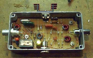


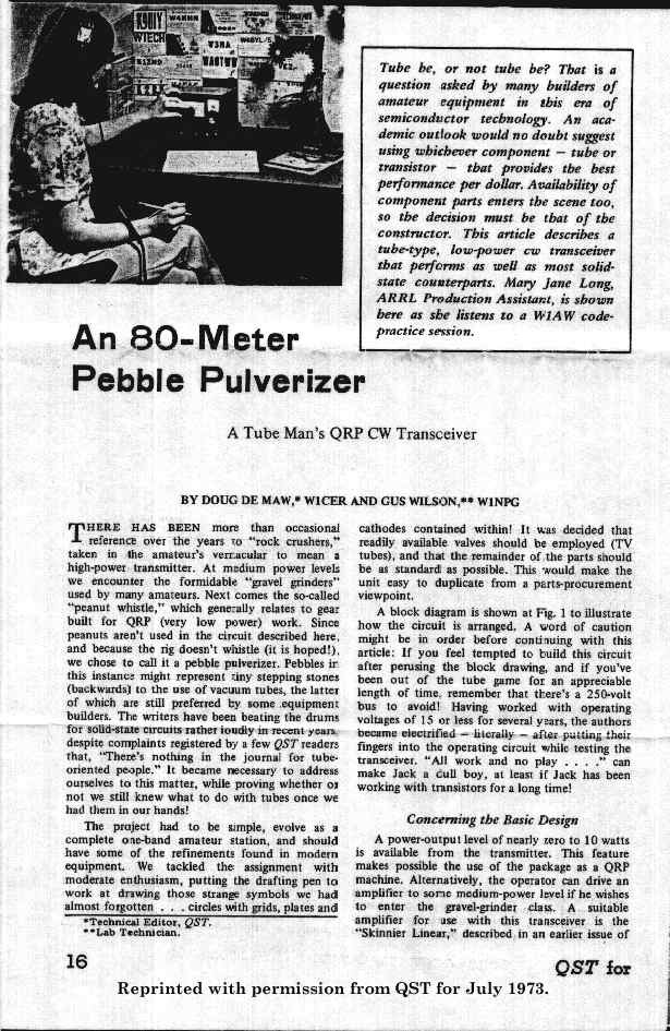
![Page 2 ] [](http://www.qsl.net/n6ev/PEBBLE2.JPG)
![Page 3 ] [](http://www.qsl.net/n6ev/PEBBLE3.JPG)
![Page 4 ] [](http://www.qsl.net/n6ev/PEBBLE4.JPG)
![Page 5 ] [](http://www.qsl.net/n6ev/PEBBLE5.JPG)
![Page 6 ] [](http://www.qsl.net/n6ev/PEBBLE6.JPG)
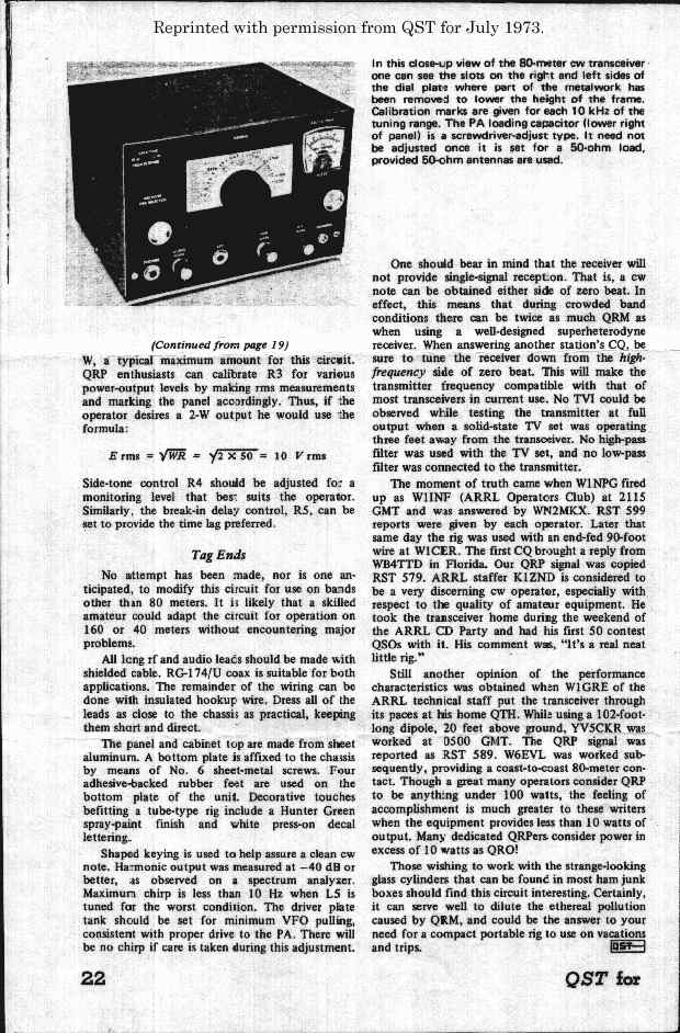
![Page 2 ] [](http://www.mnsinc.com/bry/hamscans/6t9_12.gif)
![Page 3 ] [](http://www.mnsinc.com/bry/hamscans/6t9_13.gif)
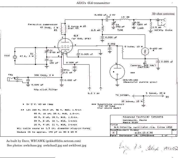
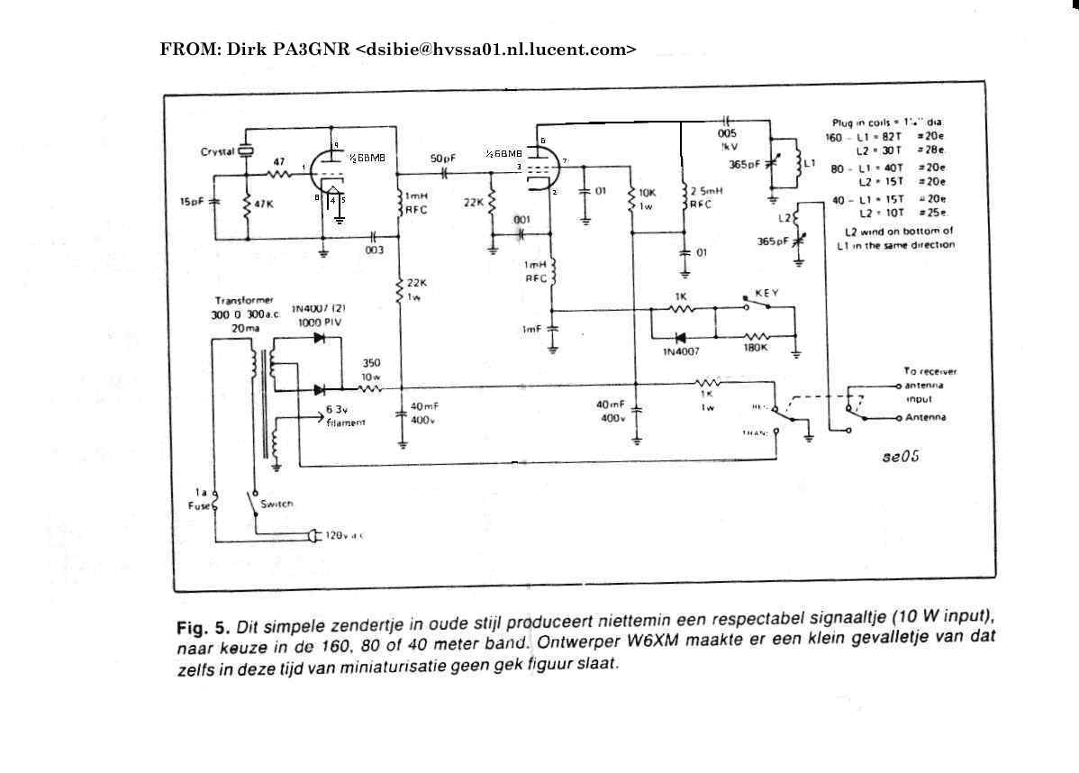