|


| |

In 1990, OSHA commissioned a report and study to be performed on
the affects EMR has on instrumentation. Pursuant to the report that they
received, it became a requirement for Tower service companies and communications
companies to have an understanding of these affects in order to insure safe
operation when working on and around communications equipment.
|
|
— FIELD SERVICE MEMO —
ELECTROMAGNETIC RADIATION
and
HOW IT AFFECTS YOUR INSTRUMENTS
May
20, 1990
|
May 20, 1990
OSHA Cincinnati Laboratory
(now the Cincinnati Technical Center)
Cincinnati, Ohio
FIELD
SERVICE MEMO
ELECTROMAGNETIC RADIATION
AND
HOW IT AFFECTS YOUR INSTRUMENTS
PURPOSE:
The purpose of this field service memo is to provide OSHA compliance
officers with basic principles of electromagnetic (EM) radiation. It
discusses the effects of radio frequency interference (RFI) on the
operation of industrial hygiene instruments, explains why special
isotropic probes are used for making non-ionizing radiation surveys, and
emphasizes the need for special attention in measuring radio frequency
fields.
PREFACE: Some discussion of the following subject matter has been
simplified for the sake of handling the subject in this limited space.
If this is your first exposure to the subject, some terms and concepts in
this memo might be unfamiliar to you. By reading the entire service memo
completely at one sitting, some of your initial questions raised in one
section may get answered in subsequent sections. Once you make it through
the material one time, it is recommended you read the entire service memo
over again a second time at another sitting.
I. WAVES IN GENERAL AND ELECTROMAGNETIC
WAVES:
Electromagnetic radiation is a wave phenomena. Before attempting to
understand electromagnetic radiation, let's first review a few properties
of waves. A "wave" is a disturbance that is a function of time
and/or space. A wave moves through a medium or space and transfers energy
from point to point as it moves.
"Wave
motion can be thought of as the transport of energy and momentum from one
point in space to another without the transport of matter. In mechanical
waves, e.g., water waves, waves on a string, or sound waves, the energy
and momentum are transported by means of a disturbance in the medium that
is propagated because the medium has elastic properties. On the other
hand, in electromagnetic waves, the energy and momentum are carried by
electric and magnetic fields, which can propagate through a vacuum."
"Although the variety
of wave phenomena observed in nature is immense, many features are common
to all kinds of waves, and others are shared by a wide range of wave
phenomena.[1]
The "size" or "height" of a water wave is called its
amplitude and tells us of its strength. All waves can be described in
reference to their "amplitude" or "strength". As a
wave travels (propagates) out from the source, the total energy radiated
from the source remains the same, but the strength of the wave decreases
as the distance from the source increases. A classic two dimensional
example shows the ripple rings expanding out from a disturbance over the
surface of a calm pond. Three dimensional waves require going one step
farther by imagining expanding spheres instead of expanding rings. As the
wave travels from the center disturbance, the wave energy is spread out
thinner over larger areas, resulting in less energy per unit area, thus
decreased "strength". The total energy stays the same, but it is
distributed over a larger area.
Now let's "switch gears" and look at another property of waves.
If we could observe a wave as it passes by a point in space, we would
notice the amplitude of the wave changing with time in a periodic or
cyclical manner. Because a wave is periodic, we can count the number of
complete wave cycles that pass by that point each second. This would be
the "frequency" of the wave.
"Frequency" is measured in Hertz (Hz), wave cycles per second.
All waves are composed of at least one sine wave or frequency element.
Waves that have non-sinusoidal looking waveforms are actually a
combination of two or more sine waves of different frequencies
NOTE: Mathematics
shows us that every wave shape is actually a combination of individual
sine waves of different frequencies. A whole area of mathematics called
"Fourier Analysis" is dedicated to analyzing the sinusoidal
component frequencies of waveforms.
Electromagnetic radiation is a wave phenomena and has all of the above
qualities of waves. An electromagnetic (EM) wave can be defined as a
"wave characterized by variations of electric and magnetic
fields". [2]
EM waves can travel through space while carrying energy at the speed of
light. Many people think of them simply as radio waves, but EM waves cover
a much broader frequency spectrum. EM waves extend from the very lowest
frequency (Hz) to frequencies beyond radio waves, light waves, X-rays, and
gamma rays.1 This broad energy range is know
as the electromagnetic spectrum. Depending on their frequency, EM waves
are known as radio waves, heat rays, light rays, etc. In this field
service memo, we will be mostly concerned with radio waves ranging from 10
kHz to 3 GHz. A diagram of this portion of the spectrum is shown in Section
VIII, Figure
2.
While radio frequency EM waves are intentionally generated by cellular
phones, walkie talkies, garage door openers, radio stations, and
television (TV) stations, they are unintentionally generated by electric
motor brushes, ignition systems of gasoline engines, medical equipment,
computer systems, and lightning. Even the sun produces radio frequency
electromagnetic radiation. The effects of unintentionally generated EM
waves will be discussed in Section
VII and Section
VIII.
II. UNITS:
All electromagnetic fields (EM waves) consist of two component fields,
electric fields (E fields) and magnetic fields (H fields). E fields and H
fields are companions and together make up the total EM field. Where one
is, so is the other. Electric field strength (E) is measured in units of
volts per meter (V/m). Magnetic field strength (H) is measured in amperes
per meter (A/m).
Power is the time rate of energy transfer. This applies to waves, too.
Radiated power is that power given off by a radiation source (antenna) and
carried through space by the EM wave. Power is measured in watts (W).
Power density is the amount of power distributed over a given unit area
perpendicular to the direction of travel. Power density is expressed in
watts per square meter (W/m2 )
or milliwatts per square centimeter (mW/cm2).
EM radiation is a periodic wave motion. The number of repetitions of the
waveform, or cycles per second, is called the frequency and is measured in
Hertz (Hz). 1 kilohertz (kHz) = 1000 Hz, 1 megahertz (MHz) = 1 million Hz,
1 gigahertz (GHz) = 1 billion Hertz, 1 terahertz (THz) = 1 trillion Hertz,
etc.
Related to frequency is the term wavelength. It is the distance a wave
travels during the time period of one complete oscillation cycle. The
wavelength of an EM wave is the wave's speed of travel (usually the speed
of light) divided by the frequency of the wave. The symbol for wavelength
is
 (Lambda).
It is measured in units of length, such as meters, centimeters, angstroms,
feet, etc. The table on the next page shows the wavelength (
)
of certain frequencies (f) when the speed of transmission is the speed of
light (C), 300,000,000 meters per second (186,280 miles per second).
= C÷f. (Lambda).
It is measured in units of length, such as meters, centimeters, angstroms,
feet, etc. The table on the next page shows the wavelength (
)
of certain frequencies (f) when the speed of transmission is the speed of
light (C), 300,000,000 meters per second (186,280 miles per second).
= C÷f.
|
TABLE 1
Wavelength to Frequency Relationship
|
|
FREQUENCY (f)
|
WAVELENGTH (
= C÷f)
|
|
1Hz
|
186,280 miles (300,000
km)
|
|
10Hz
|
18,628 miles (30,000
km)
|
|
60Hz
|
3105 miles (3000 km)
|
|
1000Hz (1 kHz)
|
1863 miles (300 km)
|
|
10kHz
|
186 miles (30 km)
|
|
100kHz
|
9836 feet (3000
meters)
|
|
1000kHz (1 MHz) (AM
radio)
|
984 feet (300 meters)
|
|
10MHz
|
98.4 feet (30 meters)
|
|
27MHz (many RF
sealers)
|
36.4 feet (11 meters)
|
|
30MHz
|
32.8 feet (10 meters)
|
|
100MHz (FM radio)
|
9.8 feet (3 meters)
|
|
300MHz
|
3.28 feet (1 meter)
|
|
1000MHz (1GHz)
|
11.8 inches (30 cm)
|
|
2.45GHz (Microwave
ovens)
|
4.8 inches (12.2 cm)
|
|
10GHz (Satellite data
links)
|
1.18 inches (3 cm)
|
|
400THz (Visible light,
red)
|
0.03 mil (0.75
 m;
7500 angstrom) m;
7500 angstrom)
|
|
750THz (Visible light,
purple)
|
0.017 mil (0.4
m;
4000 angstrom)
|
|
3,000,000THz (X-rays)
|
0.00000392 mil (0.1nm;
1 angstrom)
|
|
50,000,000THz (Gamma
rays)
|
0.000000235 mil
(0.006nm; 0.06 A)
|
III. RELATIONSHIP BETWEEN ELECTRIC AND MAGNETIC FIELDS:
Understanding electromagnetic field relationships is difficult, but
compliance officers are faced with measuring these fields. It is critical
for us to know and understand what the EM field components are and the
relationship between them so that meaningful measurements and accurate
data are taken.
As mentioned earlier, electromagnetic fields (EM
waves) are composed of two types of fields, electric fields and magnetic
fields. The relationship of electric fields to magnetic fields can be
compared to the relationship between voltage and current in a simple
electric circuit. The electric (E) field is much like the electric voltage
potential (E) of an electric circuit. The magnetic (H) field is much like
the electric current (I) of an electric circuit.
NOTE: In this text, the symbol "E" usually refers to the
electric field component of an EM field. In a few cases where it is used
for electric voltage potential "E", it will be specifically
identified and will usually be accompanied by "I" (electric
current).
Electric voltage potential and electric
current are measured in volts and amperes respectively; E fields and H
fields are measured in volts per meter and amperes per meter,
respectively. Where there is electrical current flowing, there also is a
voltage associated with it. Where there is an H field, there also is an E
field associated with it.
The complete mathematical relationship between E fields and H fields is
complicated and involves terms expressed in 4 dimensions. The complete
mathematical picture is too involved for this field service memo. However,
most applications allow for the math terms to be reduced to simple
formulas.
Under the simple conditions of wave travel through free space, the
relationship of electromagnetic fields is reduced to:
E = H x 377 (Under free space conditions.)
|
where
|
E = the electric field
strength,
H = the magnetic field strength,
377 = the characteristic impedance of free space,

a constant with units expressed in Ohms.
|
The equation for electromagnetic waves in free space, E = H x 377, and the
equation for Ohm's Law, E = I x R, are very similar. Both equations are
special case simplifications of some very complex mathematical statements
defining electromagnetic theory. Fortunately, some very intelligent men
have reduced this math into a few simple formulas like these, which we can
use under certain ordinary conditions. Three of these men are Maxwell,
Gauss, and Ohm. Thanks to them, we don't have to be expert mathematicians
to make electromagnetic surveys. If you are familiar with Ohm's law, Appendix
C, "Comparing the E = H x 377 Equation with E = I x R," may
be helpful in understanding the electromagnetic field equation given
above.
As an electromagnetic wave travels through space, energy is transferred
from the source to other objects (receivers). The rate of this energy
transfer depends on the strength of the EM field components. Keeping it
simple, the rate of energy transfer per unit area (power density) is the
product of the electric field strength (E) times the magnetic field
strength (H).
|
Pd
|
=
|
E
|
x
|
H
|
|
Watts/meter2
|
=
|
Volts/meter
|
x
|
Amperes/meter
|
|
where
|
Pd = the power density,
E = the electric field strength in volts per meter,
H = the magnetic field strength in amperes per meter.
|
The
above equation yields units of W/m2 . The units of mW/cm2 are more often used when making surveys. One mW/cm2 is the same power density as 10 W/m2 The following equation
can be used to obtain these units directly:
Pd = 0.1 x E x H mW/cm2
The simple relationships stated above apply
at distances of about two or more wavelengths from the radiating source.
This distance can be a far distance at low frequencies, and is called the
far field. Here the ratio between E and H becomes a fixed constant (377
Ohms) and is called the characteristic impedance of free space. Under
these conditions we can determine the power density by measuring only the
E field component (or H field component, if you prefer) and calculating
the power density from it.
We take advantage of this fixed relationship when we measure potentially
hazardous EM fields during an RF hazard survey. Exposure hazards that are
due to absorption by the human body are ultimately evaluated with respect
to the actual energy absorbed. Since power is the rate of energy transfer,
and the squares of E and H are proportional to power, E2 and H2 are proportional to the energy transfer rate and the
energy absorbed by the subject. Because compliance officers find it
convenient to measure EM fields in terms of E2 and H2 survey meters usually readout in terms of E2 or H2 .
Electromagnetic field exposure limits which were set for human exposure
are listed in ANSI C95.1-1982 [4]
as Radio Frequency Protection Guides (RFPG). There, values for
electromagnetic field levels are listed in terms of E2 , H2 and equivalent power density. These values are based
on the rate of energy absorbed into the human body. The term Specific
Absorption Rate (SAR) is used in the standard to describe this absorption
rate. There is a very good discussion of SAR measurements in ANSI C95
(1990) [5].
More discussion of SAR will be presented in a follow-up field service memo
which will be issued at a later date, "Measurement Practices for
Non-ionizing Radiation Surveys".
IV. PROPAGATION OF ELECTROMAGNETIC ENERGY:
Most people, including most electrical engineers, think of electricity as
electrons flowing in a wire, much like water flowing in a hose. The idea
of electrical energy moving through free space in a wave is a completely
foreign concept. Yet, electromagnetic radiation is exactly that,
electrical energy moving through space as a wave, and electrical energy in
a wire is a special case in which the energy is guided by a wire. Some of
the energy is internal to the wire, and some of the energy is external to
the wire. When we plug an appliance into the receptacle, the power
delivered to the appliance does not actually "go through the
cord", but is electromagnetic energy being "guided" by the
electron activity in the power cord. The electromagnetic energy delivered
to the load is external to the wire. The electron activity oscillating
back and forth in the wire is a result of the external electromagnetic
energy and in turn serves as a way of telling the electromagnetic wave to
follow the wire. The electron movement in the wire is proportional to the
strength of the wave being guided. Don't be disturbed if you have
difficulty grasping this concept. Even engineering students have
difficulty understanding it.
Fortunately, to analyze and solve most problems in DC and low frequency AC
circuits, it is sufficient to apply the simple Ohm's law equation.
Normally it does not require thinking in terms of electromagnetic fields.
Low frequency electromagnetic field theory is typically applied only when
analyzing the coils of relays, inductors, transformers, and motors.
Electromagnetic wave theory becomes more important as frequency climbs
into the Megahertz range, such as in analyzing wireless electromagnetic
energy transmission, radio frequency circuits, light wave analysis, etc.
EM waves can travel without the guiding action of wires. The points where
EM waves leave the guiding influence of wires and move to free and
unbounded travel are called antennas. Antennas act as coupling points for
electromagnetic energy to leave the guidance of wires for free space, and
visa versa. The area near this coupling activity is exactly where
compliance officers have to deal with electromagnetic fields, as in the
case of RF heat sealers. In general, an antenna might be one of the
conductors in an electronic circuit, a metal object such as your front
porch railing, or even nonmetallic objects like a tree limb or an extended
arm. The effectiveness of an antenna to transmit or receive EM waves
depends on the conductivity of the material used, the antenna's shape, and
the physical dimensions of the antenna relative to the wavelength of the
EM field.
The best broadcast and reception of EM waves is obtained when the
dimensions of the antenna properly match the wavelength of the
electromagnetic field. That is why the length of TV "rabbit ear"
and "whip" antennas need adjustment each time the channel is
changed, and why roof mounted TV antennas have so many different sized
elements.
When measuring worker exposure to non-ionizing radiation (EM fields), it
is important to be aware that the probe is also an antenna. The antenna
and circuitry of an RF probe are arranged so it can function over a range
of operational frequencies. The width of this operational frequency range
is called the bandwidth. If measurements are attempted outside the probe's
frequency range, the measurements will be inaccurate and could severely
damage the probe. Always choose the proper probe based on both power
rating and the frequency.
V. POLARIZATION OF THE ELECTROMAGNETIC FIELDS:
Polarization is another important concept to keep in mind when making
electromagnetic measurements. Polarization explains why walkie talkie
antennas need to be pointed in the same direction to get best reception
and why the probes of RF survey meters must be rotated while you are
making measurements.
It should suffice here to define polarization as a characteristic of
radiated EM waves which deals with the direction and amplitude
relationship of the E field "vector" in relation to the
direction of travel.
NOTE: A vector is a mathematical representation of a force
or other quantity in terms of both direction and strength.
It is because of this characteristic that we
usually use an "isotropic" probe as the receiving antenna when
performing a non-ionizing radiation survey. An isotropic probe receives
electromagnetic signals regardless of polarization or direction of travel.
An isotropic probe is designed to give the same reading, no matter which
way it is pointed in the EM field.
Since no probe is perfectly isotropic, survey probes should be rotated
about the axis of its handle during measurements (use a rotating wrist
motion like you would to turn a door knob). An average of the minimum and
maximum reading is used as the reading value.
EM wave reflections caused by metal beams, gratings, etc. can cause a
phenomenon called "multipath interference". The reflected wave
can have different polarization than the original wave. This can have
significant interference impact on the measurement results as the probe is
moved from point to point. Therefore, it is good practice not only to
rotate the probe, but also to move the probe about in a circular pattern
to obtain a general sampling of the area. As the measurements are made
closer to the radiating source, it is even more important to carefully
survey the general area to find any such localized radiation beams.
Polarization is discussed in greater detail later in Appendix
D, "More on Polarization."
VI. NEAR-FIELD VS FAR-FIELD:
Certain behavior characteristics of EM fields dominate at one distance
from the radiating antenna, while a completely different behavior can
dominate at another location. Electrical engineers define boundary regions
to categorize behavior characteristics of electromagnetic fields as a
function of distance from the radiating source. These regions are: the
"Near-Field", "Transition Zone", and
"Far-Field". The regional boundaries are usually measured as a
function of the wavelength. Figure 1 shows these regions and boundaries.
Two things should be stressed: these regions categorize behaviors which
vary even within each region; and the boundaries for these regions are
approximate "rules of thumb" (more precise boundaries can be
defined based primarily on antenna type and antenna size, and even then
the experts differ).
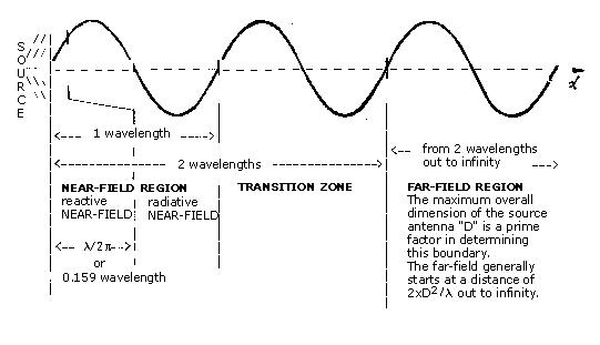
Figure 1. Antenna field Regions for Typical Antennas
FAR-FIELD: The region extending farther than 2 wavelengths away
from the source is called the "Far-Field". In the far-field, E,
H, and power density are related by the equations: E = H x 377 and Pd = E x H. These equations were explained in Section
III. Combining these two equations together we get:
Pd = H2 x 377 and Pd = E2÷377
|
where Pd
|
=
|
the
power density in watts per square meter (one W/m2 is equal to 0.1 mW/cm2 ),
|
|
H2
|
=
|
the
square of the value of the magnetic field in amperes squared
per meter squared,
|
|
E2
|
=
|
the square of the value of
the electric field in volts squared per meter squared.
|
The above
equations show that in the far-field, all
you really need to measure is the E field, actually E2 . From
this measurement, the power density and value of the H field can be
calculated. For reasons explained in Section III, health compliance
measurements are more convenient to evaluate when they are measured in
terms of the square of the field strength.
TRANSITION ZONE: The region between the near-field and the
far-field is called the "Transition Zone". It has a combination
of the characteristics found in both the near-field and the far-field.
Here it may not always be necessary to measure both E and H to obtain a
good approximation of the EM field, but several measurements are needed to
characterize the field.
NEAR-FIELD: The region located less than one wavelength from the
source is called the "Near-field". Here, the relationship
between E and H becomes very complex, and it requires measurement of both
E and H to determine the power density. Also, unlike the far-field
where EM waves are usually characterized by a single polarization type
(horizontal, vertical, circular, or elliptical), all four polarization
types can be present in the near-field.
Since both the E field and the H field components of electromagnetic waves
are absorbed by living tissue, and since the relationship between E and H
is complicated in the near-field, we must measure both E and H when
evaluating near-field hazards. This includes all low frequency sources,
such as RF heat sealers.
The near-field is further divided into the "reactive" near-field and the "radiative"
near-field. The outer boundary of the reactive near-field region is
commonly considered to be a distance of 1/2
 times the
wavelength (
/2 times the
wavelength (
/2
 or 0.159 x
)
from the antenna surface. The radiative near-field covers the remainder of
the near-field region, from
/2 or 0.159 x
)
from the antenna surface. The radiative near-field covers the remainder of
the near-field region, from
/2
 out to
(one
full wavelength). out to
(one
full wavelength).
In the reactive near-field (very close to the antenna), the relationship
between the strengths of the E and H fields is too complex to predict.
Either field component (E or H) may dominate at one point, and the other
way dominate at a point only a short distance away. This makes it
extremely difficult to find the true power density there. Not only would E
and H both have to be measured, but a new term called the phase
relationship between E and H is needed. Present survey meters (such as
OSHA's Narda and Holaday units) measure only the magnitude E or H, not
this phase relationship. Although it would be very helpful to know the
true power density, our present compliance efforts do not require us to
determine it. During a compliance survey, both the E field and the H field
components are measured separately, read from the meter as E2 and H2 quantities, and each
quantity is compared individually against the Radio Frequency Protection
Guides (RFPG) of the ANSI C95.1-1982 standard. If either the E field or
the H field component exceeds the limits of the RFPG, the level is
considered high.
As you might have guessed, the reactive near-field region has another
surprise in store for you. In this reactive region, not only is the EM
wave being radiated outward into space, but there is a
"reactive" component to the EM field. Very close to the antenna,
energy of an unknown amount is held back and is stored very near the
antenna surface. This reactive component can be the source of confusion
and danger in attempting measurements in this region. In other regions the
power density is inversely proportional to the square of the distance from
the antenna. In the vicinity very close to the antenna, the energy level
can rise dramatically with only a small additional movement towards the
antenna. This energy can be very dangerous (even hazardous) to both humans
and measurement equipment where high powers are involved.
CAUTION: When the radiating dimensions of the antenna are much smaller
than one wavelength and/or the frequency is low (as with heat sealers), it
is especially important to be aware of the POTENTIALLY HAZARDOUS
REACTIVE FIELDS WHICH MAY EXIST IN THE REACTIVE NEAR-FIELD. Exercise
extreme caution for both your safety and the equipment when making
near-field measurements, in the case of heat sealing machines. As you move
nearer to the antenna in the reactive near-field, the energy can increase
much quicker than what is computed by the inverse-square law. Some
electromagnetic energy is stored in the near-field in the vicinity of the
antenna that can be an unsuspected source of dangerous energy. This
"reactive field" energy is especially dangerous with high power
systems. The closer to the radiating source you get, the more caution
should be exercised.
The radiative near-field does not contain any
reactive field components from the source antenna. The energy is all
radiant energy. As you move further out into the radiative near-field (one
half wavelength to 1 wavelength from the source), the E and H field
relationship does not have so many surprises as in the reactive
near-field, but the E to H relationship is still complex. Since the
radiative near-field is still part of the near-field, caution should still
be exercised in relation to personal safety and equipment safety. Metal
objects such as steel beams can act as antennas by receiving and then
"re-radiating" some of the energy, forming a new radiating
surface to consider. Not only does this new radiating surface have its own
near-field regions, the energy levels might be shockingly high. Exercise
caution near such metal objects.
All near-field readings require special attention. In general, readings
taken closer than one wavelength require measurement of both the E and H
fields. A good general rule of thumb is "Measure the E field above
300 MHz and measure both-the E field and the H field below 300 MHz".
For example, when surveying radio frequency heat sealer machinery at 27
MHz (
=
11.1 meters, or 36.4 feet), both E and H must be measured, since the
measurement is in the near-field. Two wavelengths at 27 MHz is 22.2 meters
(72.8 feet) away.
While taking measurements in the near-field, you may notice the values for
E and H vary considerably from point to point. A very strong E or H field
strength may exist only inches away from a very weak E or H field
strength. When attempting "power measurement" in the near-field,
make an effort to take both the E field and the H field
measurements at the exact same physical location, especially if
unusual peaks and valleys are observed from point to point. The variation
may be only centimeters apart or may be as much as one meter. How much
care to be taken will be obvious to you by observing the meter display for
abrupt changes.
NOTE: Throughout this section the boundaries for the near
and far-field regions have been defined only in terms of
wavelength. Actually, the boundaries are based on more. The maximum
overall dimension (D) of the radiating antenna is a prime factor in
determining these boundaries. This dimension is a physically measured
length. Above we assumed that "D" was one wavelength or less.
For antennas like the ones mounted on houses for TV (dipole antennas),
"D" would be the length of the radiating arm; and for a radar
set or heat sealer, "D" might be the maximum dimension of the
port opening (or aperture) through which the EM wave passes.
In
most situations "D" is between one-fourth to one whole
wavelength (
)
long, but there are some situations where "D" might be much
larger or much smaller than "
".
When "D" is much larger 2 than "
",
the far-field boundary is not 2
as
shown in figure 1, but is 2 D2 /
.
Far-field boundary = 2 D2/
where D = the largest radiating
dimension of the antenna
=
(lambda) one wavelength
Therefore, if the maximum overall dimension exceeds "
",
the far-field boundary extends farther out than 2
.
Thus we might be required to measure both the E and H field components,
even beyond the 2
distance or when the frequency is above the 300 MHz "rule of
thumb". But don't panic, these situations are usually the exception,
but you should be aware of their existence.
More commonly, an antenna may be such that the maximum overall dimension
(D) is much less than one wavelength. In these cases, the "radiative"
portion of the near-field region may not even exist at all. However, the
nastier "reactive" near-field still exists, and it extends out
to X/2
 from
the source. So, even in cases where "D" is much less than "
",
it is best to follow the "rule of thumb" practice of measuring both
the E field and H field for frequencies below 300 MHz. from
the source. So, even in cases where "D" is much less than "
",
it is best to follow the "rule of thumb" practice of measuring both
the E field and H field for frequencies below 300 MHz.
The boundaries shown in Figure 1. should not
to be considered rigid, but they are values obtained by consensus to help
categorize wave motion characteristics and behavior into regions.
Characteristic behavior expressed in one region is not fully excluded from
existing to a lesser extent in an adjacent region. The multiple
characteristics of the transition zone are a prime example of overlapping
behavior. The regional boundaries primarily indicate where certain
characteristics require special attention.
Perhaps in a summary we can best look at two
examples. The far-field for microwave oven emissions at 2.45 GHz is only
inches from the source, so it is sufficient to measure only the E field.
However, for radio frequency (RF) heat sealers operating at 27 MHz, both E
and H must be measured, because we are in the near-field. Even when
"D" is very small, the "reactive" near-field boundary
of
/2
 at 27
MHz is 1.77 meters (5.8 feet). Thus RF heat sealers and all near-field
measurements require special attention to both field components. at 27
MHz is 1.77 meters (5.8 feet). Thus RF heat sealers and all near-field
measurements require special attention to both field components.
VII. ELECTROMAGNETIC FIELDS AND CIRCUITRY:
This section describes two related topics, electromagnetic interference
(EMI) and electromagnetic susceptibility (EMS). The term EMI is mostly
used to describe electrical signals that are given off from one source and
interfere with the operation of another electronic appliance. Comparing
with sound waves, music to one person can be noisy interference to someone
in the next room. EMS deals with the way EMI disrupts the normal operation
of the victim appliance.
OSHA's compliance instruments are small, light-weight, and battery
operated appliances. To achieve light weight, they use small batteries and
low-power circuits. Some of the circuits use analog signals (voltages and
currents of varying amplitude) and some are digital (voltage pulses to
indicate 1's and 0's). When low power levels are used in either of these
circuits, they become more susceptible to interference from external
electromagnetic fields.
The universe is full of EM fields, and they are constantly mixing with the
EM fields that are operating our electronic circuits. When the external
field induces signals in an instrument's circuits that are significant in
relation to normal circuit signals, interference results. As the strength
of the interfering field increases and the power level of the instrument's
circuitry decreases, the probability of unwanted responses increases
significantly. The interference can cause erroneous data, unwanted
results, false alarms, or even complete shutdown of the instrument. The
effects can be totally unpredictable. Adequate electromagnetic protection
is being recognized as a critical element in design of low power
equipment.
To protect against EMI, circuits are sometimes shielded in metal
enclosures, called electromagnetic shielding. Shielding is also used to
prevent EMI from radiating out from the source. Parts of a stereo system
handling low level signals are shielded to keep out the 60 Hz hum of power
lines. Large computers are shielded to prevent the electromagnetic fields
from radiating and causing interference in other equipment. Sometimes
additional circuitry, called EMI filters, are added to redirect unwanted
signals away from sensitive circuitry. Typically, EMI filters are built
into the equipment circuitry.
A circuit's susceptibility to interfering radio waves is referred to as
its Electromagnetic Susceptibility (EMS). Instruments showing no effect
from signals at one frequency may behave totally different at another. The
instrument's physical circuit dimensions, electrical characteristics, and
shielding all influence the frequency dependency of an instrument's EMS
performance. Often manufacturers take little or no concern about EMI and
EMS until someone complains of problems well after production has begun.
Both EMI and EMS problems can be solved by good design, sufficient
testing, and proper safeguards by the user.
VIII. A PROBLEM FOR OSHA COMPLIANCE AND ACTION BEING TAKEN:
Veteran compliance officers will agree that EMS has not been a significant
problem with older instruments. The circuitry operated at power levels
high enough that the effects of external fields were not noticed. OSHA's
newer instruments consume less power and are more portable, but are more
likely to be susceptible to EMI. EMI problems were experienced with the
original purchase of DuPont Mark 1 dosimeters and caused 400 units to be
recalled and modified. To avoid having another such recall, instruments
are now being thoroughly tested by the Cincinnati Laboratory for EMS
before purchase. Examples of instruments recently tested are
audiodosimeters, combustible gas meters, air sampling pumps, and air
velocity meters.
As a result of this testing, many manufacturers have become aware of EMS
and have begun designing instruments to reduce the susceptibility.
However, EMS is still not getting proper attention by some manufacturers
of industrial hygiene instruments. Some instruments show degraded
performance when exposed to EM field strengths as low as 0.01 mW/cm2 . By comparison,
the OSHA worker safety standard of the 1970's is 10 mW/cm2 , and the ANSI C95.1-1982 standard is 1 mW/cm2 for frequencies of greatest concern to us. While
non-ionizing radiation levels in violation of this OSHA standard are not
very common, the lower levels found to effect some industrial hygiene
instruments are more common. It is reasonable to expect OSHA's instruments
will be exposed to these levels. Figure 2. graphically shows these levels.
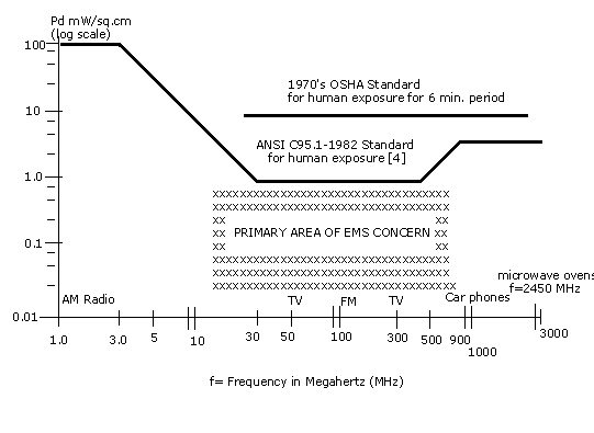
Figure 2. Plot Showing RF Levels for EMS Concern (Pd is Power Density in mW/cm2)
In the presence of an electromagnetic field,
degraded instrument performance shows itself as anything from subtle
deviations to gross errors, or even complete failure of the instrument.
Symptoms of interference may include: false alarming of the instrument,
changes in reading with no obvious cause, intermittent failures, illogical
displays, etc. Even when these obvious symptoms are absent, EMS caused
errors can still degrade the accuracy of the instrument readings.
To assure OSHA's new instruments meet minimum criteria for EMS
susceptibility, the OSHA Cincinnati Laboratory performs EMS tests on
portable instruments being considered for purchase by OSHA. This is part
of the laboratory's equipment evaluation program. Existing equipment is
also scheduled for EMS testing to verify accurate performance. This
testing is done in a special chamber called a Transverse Electromagnetic
(TEM) Cell.
IX. CONCLUSION:
Congratulations! You have now reached the end. Hopefully this explanation
has provided you with a better general understanding of electromagnetic (EM)
waves and susceptibility to unwanted electromagnetic waves. The topics are
not easy, and require complex mathematics to better understand them.
A follow up field service memo, to be issued at a later date, will
describe "Measurement Practices for Non-ionizing Radiation
Surveys". It will apply the information of this memo to the task of
taking actual field measurements of potentially hazardous radio frequency
electromagnetic fields.
X. REFERENCES
[1] Tipler, Paul A., Physics, Worth Publishers, Inc., 1982, Page
396.
[2] ANSI/IEEE 100-1984, IEEE Standard Dictionary of Electrical and
Electronics Terms, 1984, page 305.
[3] Clayton, George D. and Florence E., Patty's Industrial Hygiene and
Toxicology, John Wiley & Sons, New York, 1978, Page 448.
[4] ANSI/IEEE C95.1-1982, "American National Standard Safety Levels
with Respect to Human Exposure to Radio Frequency Electromagnetic Fields,
300 kHz to 100 GHz", 1982.
[5] ANSI C95.3(1991) "American National Standard Recommended Practice
for the Measurement of Potentially Hazardous Electromagnetic Fields - RF
and Microwave".
APPENDIX
A
ABBREVIATIONS AND SYMBOLS USED IN THIS TEXT
|
A
|
Angstrom, unit of length, one ten
billionth of a meter (0.0000000001), used only in Figure 1 on page
3. All other uses of the abbreviation "A" in this
text refer to "Amperes".
|
|
A
|
Amperes, unit of electrical current
|
|
AC
|
Alternating
Current
|
|
A/m
|
Amplitude
modulated, also
the frequency band of commercial radio extending from 535 kHz to
1605 kHz
|
|
A2/m2
|
Amperes
squared per Meter squared, in this text it is the
quantity of magnetic field strength multiplied by itself (Amperes
per Meter, quantity squared)
|
|
CB
|
Citizens
Band
|
|
cm
|
Centimeter, one hundredth of a meter (0.01
meter)
|
|
DC
|
Direct
Current
|
|
E
|
Electric, In this text, unless otherwise
identified, "E" is the electric field component of an
electromagnetic field.
|
|
E
|
Electric
voltage potential
(When "E" is used for electric voltage potential in this
text, it well identified as such. All other uses of
"E" in this text represent Electric field component of
EM fields.
|
|
E/M
|
Ratio of
the electric field (E) to the magnetic field (H), in the far-field
this is the characteristic impedance of free space, 377 Ohms.
|
|
EM
|
Electromagnetic
|
|
EMI
|
Electromagnetic
Interference
|
|
EMS
|
Electromagnetic
Susceptibility
|
|
FM
|
Frequency
modulated, also
the frequency band of commercial radio extending from 88 MHz to
108 MHz
|
|
GHz
|
Gigahertz, one billion Hertz
(1,000,000,000 Hertz)
|
|
H
|
Magnetic, In this text, unless otherwise
identified, "H" is the magnetic field component of an
electromagnetic field.
|
|
Hz
|
Hertz, unit of measurement for
frequency (cycles per second)
|
|
I
|
Electric
current
|
|
kHz
|
Kilohertz, one thousand Hertz (1000
Hertz)
|
|
|
Lambda, symbol for wavelength, distance a
wave travels during the time period necessary for one complete
oscillation cycle
|
|
MHz
|
Megahertz, one million Hertz (1,000,000
Hertz)
|
|
m
|
Micrometer, unit of length, one millionth
of an meter (0.000001 meter)
|
|
m
|
Meter, the fundamental unit of length
in the metric system
|
|
mil
|
Unit of
length, one thousandth of an inch
|
|
mW
|
Milliwatt (0.001 Watt)
|
|
mW/cm2
|
Milliwatts
per square centimeter
(0.001 Watt per square centimeter area), a unit for power density,
one mW/cm2 equals ten W/m2
|
|
nm
|
Nanometer, one billionth of a meter
(0.000000001 meter)
|
|
OSHA
|
Occupational
Safety and Health Administration
|
|
Pd
|
Power
density, unit of
measurement of power per unit area (W/m2 or mW/cm2)
|
|
R
|
Resistance
|
|
RF
|
Radio
Frequency
|
|
RFI
|
Radio
Frequency Interference
|
|
RFPG
|
Radio
Frequency Protection Guides, as listed in Table 1 of ANSI
Standard C95.1-1982
|
|
SAR
|
SPECIFIC
ABSORPTION RATE, as described in of ANSI Standard C95.1-1982
|
|
THz
|
Terahertz, one trillion Hertz
(1,000,000,000,000 Hertz)
|
|
TV
|
Television, also the frequency band of
commercial broadcast extending from 54 to 72 MHz, 76 to 88 MHz,
174 to 216 MHz, and 470 to 806 MHz
|
|
V
|
Volts, unit of electric voltage
potential
|
|
V/m
|
Volts
per meter, unit
of electric field strength
|
|
V2/m2
|
Volts
squared per meter squared, in this text it is the
quantity of electric field strength multiplied by itself (volts
per meter, quantity squared)
|
|
W/m2
|
Watts
per square meter,
a unit for power density, one W/m2 equals 0.1 mw/cm2
|
|

|
Ohms, unit of resistance
|
APPENDIX
B
INVERSE-SQUARE LAW EXPLANATION
In Section
I, it was said that all waves can be described in reference to their
"amplitude" or "strength". As a wave propagates out
from the source, the total energy radiated from the source remains the
same, but the strength of the wave decreases as the distance from the
source increases.
Although much like the classic two dimensional example of ripple rings
expanding out over the surface of a pond, three dimensional waves require
going one step farther. Instead of expanding rings, we can imagine
expanding "spheres" spreading out from the source as the wave
travels from the center disturbance (sort of like concentric balloons
being inflated). The wave energy is spread out over larger and larger
areas as the radius increases, thus resulting in less energy per unit
area, decreased "strength". Because the surface area of a sphere
is 4
 r2 , the area of a sphere increases in proportion to
"r2", and energy which is equally spread out over
the surface is inversely proportional to "r2". This is known as the inverse-square law. r2 , the area of a sphere increases in proportion to
"r2", and energy which is equally spread out over
the surface is inversely proportional to "r2". This is known as the inverse-square law.
The inverse-square law is defined as: "A statement that the strength
of a field due to a point source or the irradiance from a point source
decreases as the square of the distance from the source. Note: For sources
of finite size this gives results that are accurate within one-half
percent when distance is at least five times the maximum dimension of the
source (or luminaire) as viewed by the observer." [B1]
|
|
|
The total power passing
through each surface is the same for #1, #2, and #3. However, power
density (Pd) decrease as area increases.
Pd for area #2 is 1/4 that of #1, and Pd for
area #3 is 1/9 that of #1.
Figure B-1.
|
Consider a wave propagating outward into the
3 dimensions of space, with a given surface expanding as it travels away
from the radiating source. The surface area balloons like an expanding
sphere. The area increases in pro-portion to the square of the distance
from the wave source (except in cases using parabolic dish antennas, such
as radar or satellite dishes). Since the total energy remains constant,
the energy per unit area (or energy density) decreases. Thus the
measured strength of a wave decreases as the wave propagates through
space and is spread out over larger and larger areas. As a single
receiving object moves farther from the radiating source, less energy is
transmitted between the two objects.
The inverse-square law would make long distance space communications
impossible, but parabolic dish antennas were developed to reshape and
redirect the expanding sphere-like propagation into a narrow beam. Most
ordinary industrial hygiene applications do not involve parabolic antennas
(often called satellite dishes), and an inverse-square law type of
relationship can normally be assumed.
REFERENCES
[B1] ANSI/IEEE 100-1984, IEEE Standard
Dictionary of Electrical and
Electronics Terms, 1984, page 464.
APPENDIX C
COMPARING THE E = H x 377 EQUATION WITH E = I x R
In Section
III, we discussed the relationship between electric and magnetic
fields. Because compliance officers are faced with making measurements of
these fields, it is critical to understand the basics of the relationship
between E, H, and power density. This appendix discusses the relationship
in more detail by comparing E = H x 377 with its cousin E = I x R, Ohm's
law.
The E field is much like the electric voltage potential (E) of electric
circuits, and the H field is much like the electric current (I) of
electric circuits. In electric circuits we measure E and I in units of
volts and amperes, respectively; E fields and H fields are measured in
volts per meter and amperes per meter, respectively. Where electrical
current flows, there also is a voltage associated with it. Where there is
an H field, there also is an E field associated with it.
The equation for electromagnetic waves in free space, E = H x 377, and the
equation for Ohm's Law, E = I x R, are very similar. Both equations are
special case applications of some very complex mathematical statements
defining electromagnetic theory. During the 18001s, mathematicians and
scientists formulated equations to express the mathematical relationships
associated with electromagnetic waves. These equations predict the
behavior of EM waves. Three men who were major contributors to this work
are K.F. Gauss, G.S. Ohm, and James Clerk Maxwell. Hertz later verified
Maxwell's work experimentally. By applying specific conditions, such as
for an EM plane wave traveling through free space, formulas like E = H x
377 flow from the more complicated math. E = I x R applies the principles
to conducting mediums (electric circuits). (Most text books on
electromagnetic wave theory, such as Jordan and Balmain's book listed as
reference [C1],
discuss this in great detail.)
Under simple free space conditions, Maxwell's
equations can be reduced to:
E = H x
377 (Under free space conditions.)
and Pd = E x H W/m2 or
Pd = 0.1 x E x H mW/cm2
|
where
E
|
=
|
the
electric field strength in Volts/meter,
|
|
H
|
=
|
the
magnetic field strength in Amperes/meter,
|
|
377
|
=
|
the
characteristic impedance of free space, Z0
|
|
Pd
|
=
|
the
power density in W/m2 or
mW/cm2 as
appropriate.
|
Under simple circuit conditions at low
frequencies, the following equations
apply:
|
E
= I x Z
|
or
|
E
= I x R
|
(when
Z is resistive)
|
|
|
and
|
P
= E x I Watts
|
(when
Z is resistive)
|
|
where
E
|
=
|
the
electric voltage potential in Volts,
|
|
I
|
=
|
the
electric current in Amperes,
|
|
Z
|
=
|
the
circuit impedance (resistive and reactive) in Ohms,
|
|
R
|
=
|
the
circuit resistance in Ohms,
|
|
P
|
=
|
the power in Watts.
|
The similarities between the Ohm's law for electric circuits and free
space conditions for EM fields are obvious when compared side by side:
|
Circuits
|
EM Fields
|
|
Voltage
potential (E), Volts
|
Electric
field strength (E), Volts/meter
|
|
Electric
current (I), Amperes
|
Magnetic
field strength (H), Amperes/meter
|
|
Circuit
Impedance (Z), Ohms
|
Characteristic
Impedance (Z), Ohms
|
|
Circuit
Resistance (R), Ohms
|
Impedance
of free space (Zo=377),
Ohms
|
|
E = I x Z Volts
|
E = H x Z Volts/meter
|
|
When Z = resistive:
|
When in the far-field, Zo = 377 Ohms:
|
|
E = I x R Volts
|
E = H x 377 Volts/meter
|
|
and P = E x I Watts
|
and Pd = E x H Watts/meter2
|
|
Substituting for E and I:
|
Substituting for E and H:
|
|
P = I2 x R Watts
|
Pd = H2 x 377 Watts/meter2
|
|
P = E2/R Watts
|
Pd = E2 /377 Watts/meter2
|
The above
comparison may help you better understand the relationship between E
fields and H fields, if you already are familiar with electric circuit
theory.
The simple free field relationships stated above apply at distances of
about two or more wavelengths from the radiating source, called the
far-field. Here Z (the ratio of E to H) is a fixed constant equal to 377
Ohms, and here we can determine the power density by measuring only the E
field (or H field) and then calculate the power density from it. Survey
meters usually readout in terms of E2 or H2 Power density is E2 divided by 377 or
is H2 times 377 under these conditions.
NOTE: The above does not apply when dealing in the near-field, because
in the near-field Z is not usually equal to 377 Ohms or anything close to
it. In fact, in the near-field, Z can have any value from 0 to infinity,
and can change very quickly from one measurement position to another. That
is why both E and H must be measured when we are making measurements in
the near-field.
REFERENCES
[C1] Jordan, Edward C. and Balmain, Keith G., Electromagnetic Waves and
Radiating Systems,
Prentice-Hall, Inc., 1968, Pages 103, 118, & 120.
APPENDIX D
MORE ON POLARIZATION
Polarization is an important concept in making electromagnetic
measurements. It explains why walkie talkie antennas need to be pointed in
the same direction to get best reception and why RF survey probes must be
rotated during measurements.
Polarization of a radiated wave is
"That property of a radiated electromagnetic wave describing the
time-varying direction and amplitude of the electric field vector:
specifically, the figure traced as a function of time by the extremity of
the vector at a fixed 1 location in space, as observed along the direction
of propagation."1
The
above definition can be confusing. The following discussion can be used to lessen that confusion and give you a better feel
of this important concept.
Radiated EM waves traveling through space have a property called
polarization. It effects the compatibility of waves and certain types of
antennas. There are several things which cause some antennas to accept one
wave and reject others:
1.
The physical size of an antenna influences what wavelength (or what
frequency) will be efficiently radiated or received by that antenna.
2.
The shape of the antenna helps determine the directivity of an
antenna. Directivity involves the compass direction at which an antenna
radiates or receives EM waves.
3.
The property of polarization describes the angular pointing of the
EM field vector.
All three of these properties (physical size, directivity, and
polarization) are separate and distinct properties. The following pages
will concentrate on the topic of "polarization".
There are several types of polarization: elliptical, circular, and linear.
The polarization type is determined by the angular pointing of the
electric field vector.
To determine the polarization type, one imagines observing the tip of the
time-varying electric field vector from a fixed point in space along the
direction of the wave's propagation (This can be visualized better later). The image traced by this
vector tip is usually elliptical, but commonly the ellipse becomes a
circle or a straight line.
The following illustration may help in visualizing polarization of EM
waves:
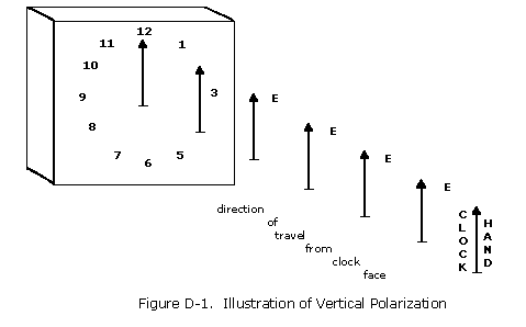
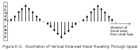
As shown in Figure D-1, we can imagine a clock face with one hand pointing
straight up at the 12 o'clock position. Let the hand move out away from
the clock face. Immediately after the first hand leaves the clock face,
let a second one replace it on the clock and also move out away from the
clock face. Repeat this again and again until a steady stream of clock
hands are flowing away from the clock, all pointing upward at the same
angle. The clock hands are representative of the vector of a vertically
polarized electric field as it moves out from the source.
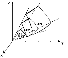
EM waves vary in amplitude during the period of one cycle. This variation
repeats over and over again for each cycle of the wave as it is radiated.
Let us move ourselves from our viewing position to a new position, one
looking at the side of the clock. If we allow each subsequent clock hand
(E field vector) to vary in size (amplitude) from the previous one, we get
a side view as seen in Figure D-2.
Now we can move
back to our original viewing position, as shown in Figure D-1. The vertically
pointing clock hand example is comparable to a vertically polarized
electric field. If someone were to reach out to catch one of the clock
hands, he can catch it only if his hand is positioned at the same angle
(polarization) as the clock hand coming broadside at him. Remember the
arrows are not pointed at him, but are pointing up and down. If his hand
is turned sideways, different from the angle of the clock hands, he would
not be able to catch any. If his hand is oriented vertically, he can catch
a vertical arrow, but not a horizontal arrow, and conversely.
Just as the pointing of the electric field vector determines the EM
field's polarization, the H field is also dependent on the E field's
vector. To help see this, add another hand to the clock face so there are
now two hands on the clock, perpendicular to each other, as in figure D-3.
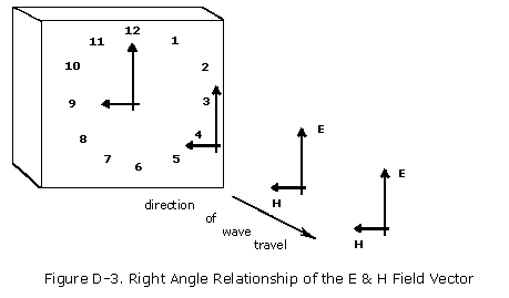
The two clock hands in Figure D-3 represent the E field and
the H field vectors. If one hand is positioned at 12 o'clock and is called
the E field vector, the other hand to the 9 o'clock position would be the
H field vector. The two vectors are at right angles to each other. Since
polarization is determined by the E field vector, the illustrated
polarization is vertical. (If the E field vector was pointed to the 3
o'clock position, the polarization would be horizontal. If the E field
vector is rotating, the polarization is circular or elliptical.) Unlike
ordinary clocks, the clock in Figure D-3 requires the two hands always be
locked together at a 90 degree angle. The H field vector (illustrated by
the 9 o'clock hand) is always perpendicular to the E field vector. The
hands can be pointed (tilted) in any direction, but must always be
perpendicular to each other. If an antenna's orientation is tilted
sideways at an angle, the polarization of the transmitted EM field would
tilt by the same angle, but the E and H fields still remain perpendicular
to each other.
As explained in the above illustration, the polarization of
the EM field is referenced to the E field, with the associated H field at
a right angle to the E field. The transmitting antenna determines the
polarization angle of the electric field radiated from it. A citizen band
(CB) radio antenna pointed straight up would radiate a vertically
polarized wave, and a horizontal "dipole" similar to roof
mounted TV antennas would radiate a horizontally polarized wave. The best
reception is obtained when the receiving antenna is polarized (tilted) to
match the polarization of the transmitting antenna. That is why CB
antennas all point the same way, straight up.
The following experiment visually demonstrates polarization and the
importance of matching the polarization between a source antenna and the
receiving antenna:
a.
Take two pairs
of "polarized" sun glasses. They must be polarized.
b.
Use one pair to filter the light coming from a flashlight.
c.
Wear the other pair.
d.
Now tilt
your head 90 degrees sideways and notice that one head angle receives the
transmitted polarized light and the other receives none.
e.
Rotate the polarized sun glasses positioned at the light source.
f.
Now do the head tilts again and notice the polarization angle has
changed by the amount rotated in step (e).
NOTE: On a sunny day items on an automobile dashboard can
be seen reflected in the windshield, but the images are much less visible
if you are wearing polarized sun glasses (provided the windshield is
tinted). If you tilt your head while wearing the polarized sun glasses the
image reflection will appear and disappear at 90 degree angles.
When performing
a non-ionizing radiation survey, the instrument's probe is usually an
isotropic receiving antenna. An isotropic probe receives electromagnetic
signals regardless of polarization or direction of travel. Such probes are
constructed using several antennas arranged in three separate but
perpendicular planes. An isotropic probe is designed to give the same
reading, no matter which way the isotropic probe is pointed in the EM
field.
In conclusion, the clock and arrow illustration presented in this appendix
was designed to help the reader understand the difficult concept of
polarization. Electromagnetic waves do not actually transfer energy as
"arrows" or "small packets" of energy. It would be a
mistake to think of RF energy transfer as anything other than a wave whose
energy is transferred by the time variation of electromagnetic fields.
REFERENCES
[D1] ANSI/IEEE 100-1984, IEEE Standard Dictionary of Electrical and
Electronics Terms,
1984, page 328.
Footnote 1: "X-Rays originate in the
extranuclear part of the atom, whereas gamma rays are emitted from the
nucleus during nuclear transitions or particle annihilation." Both
X-rays and gamma (
 )
rays have ionizing effects on tissue. At the same time, in the case of
X-rays, " ... the electrons may interact with the nucleus of the atom
to produce electromagnetic radiation having a continuous spectrum (bremsstrahlung)."
"Gamma rays may also be produced by neutron interactions with nuclei
.... the corresponding frequencies are 2xlO^18 to 2.5xlO^21 Hz."[3] )
rays have ionizing effects on tissue. At the same time, in the case of
X-rays, " ... the electrons may interact with the nucleus of the atom
to produce electromagnetic radiation having a continuous spectrum (bremsstrahlung)."
"Gamma rays may also be produced by neutron interactions with nuclei
.... the corresponding frequencies are 2xlO^18 to 2.5xlO^21 Hz."[3]
|
|
|
|
|
|