Pass Band Filters - Front End
Because the difficulty of getting IF transformers of 10mm size, we decided to experiment a bit about these filters and how to construct them with fixed inductors and adjusted with a trimmer, both of them available in the electronic shops, leaving the home brewer free from winding coils.
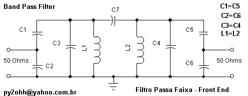
We show here a very spread type between the receiver home brewers. It is composed of a double tuned circuit coupled with capacitors and the impedance matching done with capacitive divisor. It is an equivalent circuit to that with two transformers, but the difference is only in the input and output circuits, which was inductive in the transformer case (primary – secondary) and now it is capacitive (capacitive divisor).
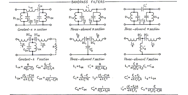
The Band Pass Circuits

Source: ARRL HandBook
Our circuit

Proceeding
Remark: those who do not like calculus can skip this part, at the end we have a link with a spreadsheet which computes the calculations
SPREADSHEET.Personally I prefer those with an inductive reactance of nearly 180 Ohms.
Those with Ľ W resistor shape and size that are available in the shops are ideal because their size and quality.
The blue ones from Sontag (molded in cubes) with values less than 8,2µH can be used till 30MHz, the values till 100µH must be used in frequencies under 3,5MHz.
They all are useful as RF chokes.
The pass band is the total pass width (in MHz)
ex. 7 MHz Frequency F = 7
and BW=1 we’ll have :
Minimum frequency = Fmin = F - ( BW / 2 )
Then
Fmin = 7- (1 /2) = 7 - 0,5 = 6,5 MHz
Similarly
Maximum Frequency = Fmax = F + ( BW / 2 )
Fmax = 7 + ( 1 / 2 ) = 7 + 0,5 = 7,5 MHz
3. Calculate XL
XL = 2 *pi * F * L
Where pi = 3,14...
F is the frequency in MHz
L the inductance in µHenries
Ex. F = 7 MHz , L=4,7
XL = 2 * pi * 7 * 4,7 = 207 Ohms
The "Q" is a factor which shows the quality or merit bigger when the pass band is more narrow Q = F / BW
Ex. F = 7 MHz and BW = 0,5
Q = 7 / 0,5 = 14
Qe is the reactance which must be expected when the filter is not connected to other circuits and permits calculating an appropriate load.
Qe = Q * Square root (2)
Ex. Q = 14
Qe = 14 * 1,7 = 19,8
6. Calculate the Filter impedance Zf
The filter impedance is the input and output filter impedance without the capacitive divisor.
Zf = Qe * XL
Ex. Xl = 207 Ohms and Qe = 19,8
Zf = 19,8 * 207 = 4098 Ohms
7. Calculate the coupling capacitor C7.
C7 (pF) = ( 1000000 * ( Fmin + Fmax ) ) /
( 4 * pi * Fmin * Fmax * Zf )
Where Fmin and Fmax are in MHz
8. Calculation of the capacitive reactance of C1 XC1
This is the most suitable reactance to the coupling
XC1 = Square Root ( Zf * Zin - ( Zin * Zin) )
Where Zin is the input impedance, usually 50 Ohms.
9. Calculation of the capacitor C1
C1 (pF) = 1000000 / ( 2 * pi * F * XC1 )
C2 = (square root ( Zf * ( C1 * C1 ) / ( Zin) ) ) - C1
It is the capacitor which resonates with L in the filter frequency
Then Xct = XL that is the reactance must be the same for resonance to be.
Ct (pF) = 1000000 / ( 2 * pi * F * XL )
Because the influence of other capacitors, we must calculate the value that they show in the LC circuit.
Ceq = ( C1 * C2 ) / ( C1 + C2 )
That is the equivalent capacitor value substracted from the total tuning capacitor value.
C3 (pF) = Ct - Ceq
See also:
fendsimplificado.htm a simplified pass band filter(30, 40 and 80m) divisorcapacitivo.htm how to calculate capacitive impedance divisors divisorindutivo.htm how to calculate inductive impedance divisorPractical Fulfillment:
These filters calculation can be done with the Excel spreadsheet that we wrote for this task
filtropassafaixa.zip (in portuguese).In the calculations the capacitor C7 can be under 1pF, values until 0,5 pF (2x1pF capacitors in series) or even (3x1pF capacitors in series) can be used, but lower values make the filter not practical and new values for L or BW must be assumed.
The C3 capacitor C3 is a direct trimmer (we have found ceramic trimmers in the Sao Paulo shops) or with a suitable capacitor in parallel.
The C1 and C2 capacitors are usually composed by a parallel capacitor association, these values does not need to be exact, the differences are compensated by the trimmer in C3.
The fulfillment of filters with different input an output impedances is possible, calculating C1 and C2 for the input and output impedances.
Use preferably commercial inductors which look like 1/4 W resistors, they cost less, have a high Q and in these circuits they are not under high RF currents.
For the realization in blocks we suggest:

Results
We built filters for 40m (7MHz), for 15m (21MHz) and for 20m (14MHz) which show very near character to that calculated, probably because we use common ceramic capacitor, where the ideal would be using silvered mica NP0. The examples can be seen in the CW receiver for 15m in this site
Links
Learn more about front end and filters in :
http://www.qrp.pops.net/captap.html - calculations and theory. http://www.qrp.pops.net/bandpass.htm - theory and examples http://www.pan-tex.net/usr/r/receivers/elrnbpf.htm - examples http://www.electronics-tutorials.com/filters/band-pass-filters.htm - tutorials and calculation
Filtro Passa Faixa - Front End
Devido a dificuldade de obtenção de transformadores de FI de 10mm de tamanho, resolvemos estudar um pouco sobre estes filtros e como construi-los com indutores ajustados por um trimmer, ambos encontrados no comercio ficando o montador livre de enrolar bobinas.
Apresentamos aqui um tipo muito difundido junto aos montadores de receptores, trata-se de dois circuitos sintonizados acoplados a capacitor e o casamento de impedâncias se faz com divisor capacitivo. É um circuito equivalente aquele dos transformadores e a diferença está somente nos acoplamentos de entrada e da saída que era indutivo no caso do transformador (primário - secundário) e agora é capacitivo (divisor capacitivo).
Os Circuitos de Band Pass

Fonte ARRL HandBook
Nosso circuito

Procedimento
Nota : quem não gosta de calculo pode pular esta parte, no final temos um link para uma planilha que faz os cálculos
PULA CÁLCULO.Pessoalmente eu prefiro aqueles com reatância indutiva próxima a 180 Ohms.
Aqueles com forma e tamanho de resistores de 1/4 W, que são encontrados no comércio, são os ideais devido ao tamanho e a qualidade.
Os azuis da Sontag (moldados em cubos) com valores inferiores a 8,2µH podem ser utilizados até 30MHz, os valores até 100µH devem ser utilizados em freqüências abaixo dos 3,5MHz.
Como choque de RF todos servem.
A banda passante é a largura total passante (em MHz)
ex. Freqüência de 7 MHz F = 7
e BW=1 teremos :
Freqüência mínima = Fmin = F - ( BW / 2 )
Então
Fmin = 7- (1 /2) = 7 - 0,5 = 6,5 MHz
Analogamente
Freqüência Máxima = Fmax = F + ( BW / 2 )
Fmax = 7 + ( 1 / 2 ) = 7 + 0,5 = 7,5 MHz
3. Calcule XL
XL = 2 *pi * F * L
Onde pi = 3,14...
F é a freqüência em MHz
L a indutancia em µHenries
Ex. F = 7 MHz , L=4,7
XL = 2 * pi * 7 * 4,7 = 207 Ohms
O "Q" é um fator que mostra a qualidade ou o mérito quanto maior mais estreita a banda passante.
Q = F / BW
Ex. F = 7 MHz e BW = 0,5
Q = 7 / 0,5 = 14
Qe é a reatância que deve ser esperada quando o filtro não estiver ligado a outros circuitos, e permite calcular uma carga apropriada.
Qe = Q * Raiz quadrada (2)
Ex. Q = 14
Qe = 14 * 1,7 = 19,8
6. Calcule a impedância do Filtro Zf
A impedância do filtro é a impedância de entrada e da saída do filtro, sem o divisor capacitivo.
Zf = Qe * XL
Ex. Xl = 207 Ohms e Qe = 19,8
Zf = 19,8 * 207 = 4098 Ohms
7. Calculo do capacitor de acoplamento C7.
C7 (pF) = ( 1000000 * ( Fmin + Fmax ) ) /
( 4 * pi * Fmin * Fmax * Zf )
0nde Fmin e Fmax em MHz
8. Calculo da reatância capacitiva de C1 XC1
Esta é a reatância mais adequada ao acoplamento.
XC1 = Raiz quadrada ( Zf * Zin - ( Zin * Zin) )
Onde Zin é a impedância de entrada, normalmente 50 Ohms.
9. Calculo do capacitor C1
C1 (pF) = 1000000 / ( 2 * pi * F * XC1 )
C2 = (raiz quadrada ( Zf * ( C1 * C1 ) / ( Zin) ) ) - C1
É o capacitor que ressoa com L na freqüência do filtro.
Então Xct = XL ou seja a reatância deve ser igual para haver ressonância.
Ct (pF) = 1000000 / ( 2 * pi * F * XL )
Devido a influencia de outros capacitores, devemos calcular o valor que eles representam no circuito LC.
Ceq = ( C1 * C2 ) / ( C1 + C2 )
É o valor do capacitor equivalente subtraído do valor do capacitor de sintonia total.
C3 (pF) = Ct - Ceq
fendsimplificado.htm um filtro passa faixa simplificado (30, 40 e 80m)
divisorcapacitivo.htm como calcular divisores de impedância capacitivo
divisorindutivo.htm como calcular divisor de impedância indutivo
Realização Prática :
O calculo destes filtros pode ser feito com a planilha Excel que preparamos para esta tarefa
filtropassafaixa.zip .Nos cálculos o capacitor C7 pode ter valores abaixo de 1pF, valores até 0,5 pF (2 capacitores de 1pF em série) ou mesmo de 0,33pF (3 capacitores de 1pF em série) podem ser utilizados, mas valores menores tornam o filtro não realizável e novos valores de L ou BW devem ser assumidos.
O capacitor C3 é um trimmer direto (temos encontrado trimmers cerâmicos no comércio de S. Paulo) ou com um capacitor adequado em paralelo.
Os capacitores C1 e C2 são normalmente constituídos de uma associação de capacitores em paralelo, estes valores não necessitam ser exatos, as diferenças são compensadas pelo trimmer em C3.
A realização de filtros com impedâncias diferentes de entrada e saída são possíveis, calculando C1 e C2 tanto para a entrada como para a saída.
Utilize de preferencia indutores comerciais que fisicamente se assemelham a resistores de 1/4 W, custam menos tem um Q alto e nestes circuitos não são submetidos a altas correntes de RF.
Para a montagem em blocos sugerimos :

Resultados
Montamos filtros para 40m (7MHz) para 15m (21MHz) e para 20m (14MHz) que apresentaram características muito próximas das calculadas, provavelmente porque utilizamos capacitores cerâmicos comuns, onde o ideal seria utilizar capacitores NP0 tipo PLATE (mica prateada).
Os exemplos podem ser vistos no Receptor CW para 15m, neste site.
Links
Aprenda mais sobre front end e filtros em :
http://www.qrp.pops.net/captap.html - calculo e teoria.
http://www.qrp.pops.net/bandpass.htm - teoria e exemplos
http://www.pan-tex.net/usr/r/receivers/elrnbpf.htm - exemplos
http://www.electronics-tutorials.com/filters/band-pass-filters.htm - tutoriais e cálculos