Inductive Divider / Impedance Transformers
Matching impedances
A simple method and very used by the home-brewers for impedance matching and coupling is the use of a inductive divider or transformers.
This method is generally used either with low or high involved power.
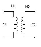
The ratio between the impedances and the primary number of turns (N1) and the secondary one (N2) is determined by the formula :
( N2 / N1 ) ^2 = Z2 / Z1

impedance transformer circuit
Example :

This circuit shows a 680 Ohms output impedance, let's say the working frequency is 7 MHz, we choose a 4.7µH Sontag molded choke.
By the table it has 21 to 22 turns.
We desire a 50 Ohms output.
We will have :
( N2 / N1 ) ^2 = Z2 / Z1
N2 ^2= (N1 ^2 ) * Z2 / Z1
N2= N1 * SQUARE ROOT (Z2/Z1)
Replacing
N2= 21,5 * square root (50/680)
N2= 21,5 * square root (0,0735)
N2= 21,5 * 0,271
N2= 5,8
N2= 6
In order to calculate C, calculate XL in the chosen frequency
XL = 2 * pi * F(MHz) * L (µH)
XL = 2 * 3,14 * 4,7 * 7 = 207
, as in resonance XC = XL, calculate L by XL
XC = 1/ (2 * pi * F(MHz) * C(µF)
Or use the resonance formula
C(Pf) = 25330 / { ( (F(MHz))^2 ) * L(µH) }
C= 109 pF
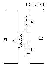
Example2 Trifilar Coils

TRIFILAR COIL
IMPEDANCE RATIO
( N2 / N1 ) ^2 = Z2 / Z1
As N2= 2 * N1
We will have
(2 * N1 / N1) ^2 = Z2 / Z1
2 ^ 2 = Z2 / Z1
4 * Z1 = Z2 or Z2 = 4 * Z1
if Z1 = 50 Ohms Z2 = 200 Ohms (4x)
Example3 trifilar coils

Trifilar coils - series
Ratio
Z2= 4 * Z1 or Z1 = Z2/4
Z3= 9 * Z1 or Z1 = Z3/9
Z3= (9/4) Z2 = 2,25 * Z2 or Z2 = Z3 / 2,25
Hope this has helped ...
73 PY2OHH Miguel
Divisor Indutivo / Transformadores de Impedancias
Casando impedancias
Um método simples e muito utilizado pelos montadores para o casamento de impedancias e acoplamentos é o uso de um divisor indutivo ou transformadores.
Este método é de uso geral com baixa ou alta potencia envolvida.
A relação entre as impedancias e o número de voltas do primario (N1) e secundario (N2) são dados pela formula :
( N2 / N1 ) ^2 = Z2 / Z1

circuito do transformador de impedancias
Exemplo :

Este circuito apresenta uma impedancia de saída de 680 Ohms, digamos que a frequencia de trabalho seja 7 Mhz, escolhemos o indutor comercial da Sontag de 4,7 MHz.
Pela tabela ele possui 21 a 22 voltas.
Desejamos uma saída de 50 Ohms.
Teremos :
( N2 / N1 ) ^2 = Z2 / Z1
N2 ^2= (N1 ^2 ) * Z2 / Z1
N2= N1 * RAIZ (Z2/Z1)
Substituindo
N2= 21,5 * raiz (50/680)
N2= 21,5 * raiz (0,0735)
N2= 21,5 * 0,271
N2= 5,8
N2= 6
Para calculo de C , calcule XL na frequencia escolhida
XL = 2 * pi * F(MHz) * L (µH)
XL = 2 * 3,14 * 4,7 * 7 = 207
, como na ressonancia XC = XL, calcule L por XL
XC = 1/ (2 * pi * F(MHz) * C(µF)
Ou use a formula da ressonancia
C(Pf) = 25330 / { ( (F(mHz))^2 ) * L(µH) }
C= 109 pF
Exemplo2 Bobinas trifilares

BOBINA TRIFILAR
RELAÇÃO DE IMPEDANCIAS
( N2 / N1 ) ^2 = Z2 / Z1
Como N2= 2 * N1
Teremos
(2 * N1 / N1) ^2 = Z2 / Z1
2 ^ 2 = Z2 / Z1
4 * Z1 = Z2 ou Z2 = 4 * Z1
se Z1 = 50 Ohms Z2 = 200 Ohms (4x)
Exemplo3 bobinas trifilares

Bobina trifilar - série
Relação
Z2= 4 * Z1 ou Z1 = Z2/4
Z3= 9 * Z1 ou Z1 = Z3/9
Z3= (9/4) Z2 = 2,25 * Z2 ou Z2 = Z3 / 2,25
Espero que tenha ajudado ...
73 PY2OHH Miguel