
|
Remote Sensing and Control System (Graduation Project -2001) |
2- Transducers
Transducer is a device that receives energy from a measurand and responds to that energy by converting it to some form for measuring system. For electronics measuring system our primary concern is to convert physical quantities into electrical form.
Sensors and transducers devices take measurements of mechanical, thermal, electrical, and chemical quantities. The sensor is responsive to changes in the quantity to be measured; for example: temperature, position, or chemical concentration. The transducer converts such measurements into electrical signals, which can be fed to instruments for readout, recording or control of the measured quantities. Sensors and transducers can operate in locations remote from the observer and in environments unsuitable and impractical for human beings. In most instances the signal is weak and must be amplified by an electronic circuit.
2.1 Transducer Types:
Active: They require external source of energy to operate. For example potentiometer requires external voltage to measure a quantity.
Passive: In Passive transducers we do not need an external power supply. For example a thermocouple need no external source. The temperature naturally affects it.
Analogue: The sensors whose output signal varies in proportion to the external factor. These types of sensor can not be directly interfaced with the computer.
Digital: The sensors which give only two types of signals when they interact with the environment. This values could mean (High / Low) or (On / Off).
Few of the very prominent sensors that could be used for this project are Temperature sensor (analogue), Light sensor (analogue), Infrared sensor (digital), Smoke sensor (analogue), Audio level sensor (analogue), Tilt sensor (digital), Object detector (digital), Water level (digital), Radio signal sensor (analogue), etc.
2.2 Criteria for selection of transducers:
Range: The minimum and maximum values that a transducer can read is known as range of the transducer or end points. More range, better the transducer.
Input threshold: The smallest detectable value that a transducer can read above zero is called the input threshold of the transducer. Smaller the input the input threshold more sensitive is the transducer.
Accuracy: Difference between the measured and the accepted values. If the difference is greater, less the accuracy of that transducer.
Repeatability: Maximum difference between consecutive measurements of the same quantity at different times. Small the difference more reliable the transducer will be.
2.3 Environmental Considerations:
Natural hazards: The factors that naturally exist and cannot be removed. For example the noise and pollution present in the atmosphere that interact with the transducer and make it less accurate.
Human caused hazards: The distortion caused by the interference of the actions caused by the humans. Like placing transducer in an electrically noisy environment.
Power requirements: Enough power should be available for the active transducer to function properly. If the power supply is not well rectified or not enough current is available for the sensor to function, the transducer will show unstable reading s at the output.
Loading Effects: Loading effect in electronics occur when when transducer having high resistance connected to the amplifier having finite input impedance. In this case signal is reduced.
Human Factor: The lifetime of the transducer depends on the operating skills, installation method, cost and required maintenance.
A special care has been taken while choosing the sensors for this project. The sensors which were difficult to construct, needed more time and effort for attenuation, showed a very uncommon purpose of usage and did not involve related electronics engineering job have been kept aside. Following four sensors have been constructed keeping in view the above points:
Temperature sensor
2.4 Temperature Sensor:
Transducer that transforms the surrounding temperature to an electrical signal is known to be temperature transducer. There are many kinds of temperature sensing transducers: For example:
Thermocouples: two metallic strips of different metals, in contact with each other, having different coefficient of expansion. These strips are graded to tell the temperature. It has a large range and accurate but they are non-linear and much calibration is required.
Thermistor: It consists of temperature dependent resistor. The conductivity of germanium is found to increase 6-8 percent per degree change in temperature. A semiconductor used in this manner is known as thermistor. Ge and Si are not used in the commercial fabrication of the thermistor because they are too sensitive to impurities. However sintered mixtures of oxides as NiO, Mn2O3 and Co2O3 are used. They need an external power supply which will calculate the current flowing through the resistance. These have negative coefficient of resistance, it is non-linear and require much calibration. But they have large range and very accurate result.
IC temperature sensors: In this project, temperature is measured by using Integrated circuit temperature sensor. These come in transistor shape or IC form. To improve accuracy, linearity and sensibility diode manufacturers have developed IC temperature sensor. These are not much accurate as thermocouples or thermisters but they are convenient and low cost. It uses Zener diode linear characteristics with the temperature. Either the current or the voltage is linear to the temperature. It has got a limited range. It can read values form -50deg.C to 150deg.C. Its easy to calibrate and output can be read directly in degrees.
As in the thermistor we have discussed that they have negative coefficient of receptivity. heavily doped semi-conductor can exhibit a positive coefficient of receptivity, for under these circumstances the material acquires metallic properties and the resistance increases due to the decrease of carrier mobility with temperature. It has temperature coefficient of resistance +0.7 % per deg.C. It works over the range of -50deg.C to +125deg.C.
Mostly Zener diodes are temperature sensitive devices. the temperature coefficient is given as the percentage change in reference voltage per degree centigrade change in diode temperature. These have positive coefficient. and the dynamic resistance is very low about 10 Ohms. IC transducer recommended to be used in this project is LM335 (precision temperature sensor).
Amplification & Attenuation:
To read the temperature we have to bring our output to a certain range, which would be common to all other transducers output. The acceptable range chosen for this project is 0-5 V.
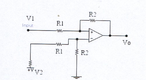
Figure 2.2
As we know from the data sheets that the output of a LM335 if connected as above at zero deg.C is 2.83 V with a power supply of 5V; At a nominal room temperature 22 deg.C the output practically read is 3.03V; further calculations will reveal that at 100 deg. the output of the transducer arrangement would be 3.83V. The difference between minimum and maximum values would be 2.83 - 3.83 = 1.00V. Such a range is too small and very much impractical. To increase this range between 0-5V as agreed above, we need to amplify using differential OP-AMP as shown in the figure 2.2.
The output voltage of an OP-AMP is given by
Vo = (R1 / R2) x (V1 - V2) ..... 2.4
Finding the correct values of R1 & R2 when V1 is the sensor reading and V2 is reference voltage of 2.83V of zero deg.C. For maximum value of V1 = 3.83 and maximum range of Vo = 5V; computing these values in the formula we get: R1 / R2 = 1 / 5. However, practically the R1 = 540K Ohm & R2 = 100K Ohm.
Further more, for any given output voltage at differential OP-AMP could be given by
TC = 100(2.83 - V1) .... 2.5
Where "Tc" is temperature in Centigrade. Through this formula, we can also check practically and plot following graph for linearity.
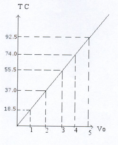
Figure 2.3
Light is but a very important portion of electromagnetic spectrum. It is the wave length to which human eye is sensitive. Vision supplies us with information both in quantity and in detail. Measurement of electromagnetic radiometry. The measurement of those aspects of radiation, which effect vision, referred to as photometry. Watt is radiometry unit where as Lumen is photometry unit. To obtain the measure if relative brightness of various sources the photometry units are used. Light is a form of energy and power. The radian energy and power are measured in Joules and Watt respectively. Radiant power is referred as flux. The flux per unit area delivered to a surface is the irradiance equivalent unit Lux is used, which is Lumen per unit area. Its the unit of light.
1 Lumen / Area (Lux) = 0.001464 Watt / sq. meter
There are many types of transducers, which measure Lux. Most commonly are the photo-resistors that are inexpensive, sensitive and can with stand high voltages. These are composed of different semiconductor materials according to the requirements. They include CdS (Cadmium Sulphur), CdSe (Cadmium Serenade) and PbS (Lead Sulphur). These three types of photo-resistors have different ranges to detect light as given in the table below:
|
Fabrication Material |
Peak response for Wavelengths |
Remarks |
| CdS (Cadmium Sulphur) | 600 nm | Visible |
| CdSe (Cadmium Serenade) | 720 nm | Visible |
| PbS (Lead Sulphur) | 2200 nm | Visible & Infrared |
A photo-resistor changes the resistance proportional to the intensity of light. Consider a photo-resistor, which show 600 Ohm at full light and 13 K.Ohm in no light. the area of exposure be 1 sq.cm; applying 1V across the Photo-resistor, the power dissipated will be given by P = V ² / R
that would be at 600 Ohm; P=1.66mW. Further to this Flux If = P / A
Where A is the exposure area of the photo-resistor. Which means If = 16.6W/m². At no light the range R=13K.Ohm and the power dissipated will be P=76µW; If = 0.76W/m² which is a negligible value. Converting it to Lux as per the above formula; the range will come to be from 500 - 12,000 Lux for that particular photo-resistor. However, no matter how careful we are in measuring brightness of light there are always many defects, three prominent ones are as following:
Diffraction: Failure of light to travel in a straight path is known as diffraction. Due to diffraction much of light could enter into the transducer and make the reading non-linear.
Total Internal Reflection: The light enters the transducer medium at different angles. At a certain angle all of the light is reflected away from the sensor. this could be considered as measurement loss.
Interference: Light consists of many frequencies and each have different amplitudes. It is very much possible that two beams of light of the same frequency and amplitude traveling in opposite direction may cancel each others effect. Or in case they have same direction their intensity will double. This is as per the wave nature to light.
Amplification & Attenuation:
There are two ways to convert or measure resistance in terms of voltage and to maintain its linearity if variable. One common way is to construct resistor bridge and second one is to use it as a gain resistance in an operation amplifier. In this project we will demonstrate using the second method as shown in the figure below. Another differential OP-AMP is connected in the circuit so as to limit the output voltage range from 0-5V.
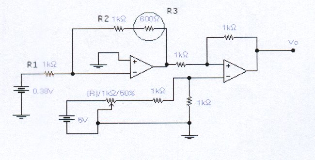
figure 2.4
Jaeger's experiment was one of the advances that paved the way for the modern smoke detectors. It was 30 years, however, before progress in the nuclear chemistry and solid state electronic made cheap sensor possible. The first commercial smoke detectors came to market was in 1969. Smoke detectors fall in two major classes. Ionization detectors, the most common units trigger an alarm after smoke particles attach themselves to ionized air molecules. In contrast, a photoelectric unit can be detect light that is scattered by smoke particles onto a photocell, thereby initiating and alarm. In another type of photoelectric device, smoke can be block a light beam. In this case, the reduction in light reaching the photocell sets off alarm.
There are two kinds of smoke detectors: ionization detectors and photoelectric detectors. Ionization detectors respond faster to the flaming fires than do the photoelectric detectors, which smell smoldering fires more quickly. Some commercial products now come equipped with both. Heat detectors are placed in kitchen which trigger alarm by the temperature sensor placed inside them.
Ionization detector, collusion between Amerciam-241 alpha particles and air molecules yield ions that allow a (small) current to flow between two electrodes. Any reduction of this current by smoke or steam sounds the alarm, The arm also sounds when a weak battery causes a reduction in the current. Americium is a man-made radioactive element. Amercium-241 was first Americium isotope isolated (by bombarding plutonium with neutrons in a nuclear reactor). It is isolated nowadays as a decay product from spent plutonium fuel. The decay of Americium-241 (half-life of 432 years) yields neptunium-237 plus alpha and gamma rays.
The radiation source comprises of Americium-241 dioxide in a gold matrix covered by silver foil. The foil is thin enough to allow particles to escape into ionization chamber. The alpha particles travel few centimeters in the air before they are absorbed and hence will not escape the smoke alarm. They do not have enough energy to penetrate the dead layer of the human skin, which is about 70 micrometers thick. The gamma rays from an unshielded smoke detector gives a radiation dosage about three thousand times lower than the natural back ground radiation to which one is exposed everyday.
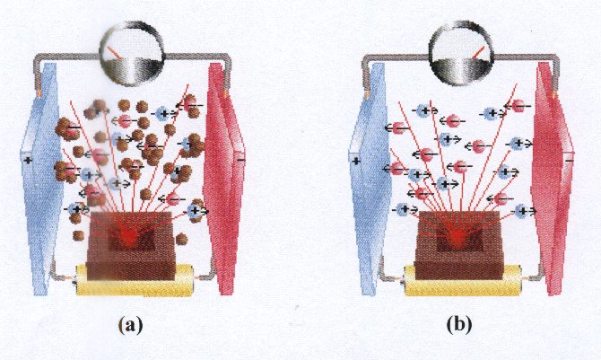
Figure 2.5
Amplification & Attenuation:
For this project we buy a smoke detector (completely ready-made). I t consists of radioactive transducer, amplifying circuit, comparator and alarm circuit. This was not only cheap but convenient as well. The amplifier circuit amplifies the voltage to specified voltage. If amplified voltage is above the specific voltage then it switches on the alarm circuit. The most important voltage is the transducer-amplified voltage, which goes to the comparator. This voltage is proportional to the physical factor (smoke). We take a separate link to this point in the circuit and before that if any alarm hooter or beeper attached to be removed. In out case as the detector unit was powered by the in-build battery of 9V, the out put of the link range was checked to give 2.3V - 3.0V under no smoke and smoky conditions respectively. The link which was taken form the smoke detector the range to be increased from of 0.8V to 5V, differential OP-AMP circuit is to be connected as in figure 2.2. Finding the values for R1 & R2 by the formula 2.4. the calculations show that (R2 = 2 x R1).
The most commonly used transducer to sense sound intensity is none other than microphones. Contact microphones are in a class all by themselves. They work on the obscure principle known as Piezo-electric effect. The Piezo-electric effect occurs when crystals are crushed. When pressure is placed on the crystal lattice, electrons are discharged as electrical energy. Contact mics are usually a disk of metal with a thin layer of crystal membrane on one side. The amount of pressure that needs to be exerted on the crystal is far more than is transmitted through the air as sound waves. The way to get right amount of pressure is to apply the disk directly to the sound source. The only disadvantage is that contact mics are not designed for musical applications, because they do not pick up all the frequencies. Aside from this the benefits of the contact mics are far outweighed than the problems.
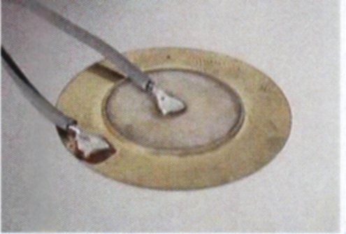
Figure 2.6
The intensity of sound is a measure of the average rate of sound energy flow per unit area across a surface perpendicular to the direction of propagation. Intensity=Rate of flow of sound energy / area = Power / Area. One Watt per square meter is too large to measure the small but wide range of sound intensity levels that the human ear is sensitive to. Special units have been designed to measure sound intensity. such as Bel and deciBel). Increase of 1 Bel means 10 times increase in intensity. Its found by:
B = log ( I / Io )
Where I is intensity in W/m² . and Io =10exp(-12) W/m² ( which is considered to be the threshold of human hearing). Intensity in deciBels is given by:
dB = 10 log ( I / Io )
An increase of 1dB is the 25% increase in the intensity and 3dB is the doubling of the intensity but its barely detectable or audible. It is useful to estimate the approximate intensity of sounds emanating from various different sources. For accurate measurements of sound intensity special instruments can be used. They are placed at standard distances (usually 1 meter) from the source, which is measured. Sound intensity decreases as the distance increases from the source.
Amplification & Attenuation:
This consists of three stages 1) Differential 2) Amplifier 3)Peak level marker. In the first stage we connect the transducer to the differential input of OP-AMP - LM4700 quad. and then followed by the non-inverted stage of the another OP-AMP - LM4700 and finally to the low pass filter consisting of capacitor and a diode to eliminate any negative part of the wave form.
![]()
Figure 2.7
With the following arrangement output at last stage min value Vo = 0.4 Vpp and max value Vo = 9.3 Vpp. These are for the initial inputs to the system where inputs are min value Vi = 0.212 Vpp and max value Vi = 0.229 Vpp. These values were taken from Oscilloscope practically. Computing amplification gain will give us the amplification range to be
A (min) = 20 log [ Vi (max) / Vi (min)] = 0.32 dB
A (max) = 20 log [ Vo (max) / Vo (min)] = 27.32 dB
A = [ 27.32 - 0.32] = 27 dB
Thus the amplifier designed is in very much practical range to any one to hear. The source voltage for the amplifiers are 5 V, therefore the output will also range in between 0 - 5 volts. It will allow us to feed this voltage into the computer.
![]()
Figure 2.8