
|
Remote Sensing and Control System (Graduation Project -2001) |
3- Designing of Analogue Multiplexer
When two or more independent messages or information-bearing signals, are carried through a single medium, or channel is known as multiplexing. When multiplexing is performed two or more channels are combined into a single channel or in a process often called de-multiplexing a single channel is divided into several sub-channels. Many different types of multiplexing are possible.
There are many types of multiplexing techniques used according to the requirements. The most commonly used are:
Frequency-Division Multiplexing: A single frequency channel is sub-divided into two or more sub-channels, each which can carry a smaller range of frequencies than the original signal. Frequency division multiplexing is used in television broadcasting, when audio and video signals share a single channel; and in microwave transmission of a long distance telephone calls, when 60 or more conversations are carried out by a single microwave beam.
Time Division Multiplexing: A second type of multiplexing is a time division multiplexing, in which successive time intervals are used for the transmission of messages over a single channel. When information can be stored into or retrieved from the computer's memory at a much greater rate than it can be supplied or used by an external device such as a card reader, printer or teletype terminal, several such low-speed devices can share a single multiplexed data channels.
Statistical time division Multiplexing: In Statistical time division multiplexing (STDM), time slots are assigned to signals dynamically to make better use of bandwidth.
Wave Length division Multiplexing: Each signal is assigned a particular wave length; used on a optical fiber.
Designing Low Frequency 8-Channel Analogue MUX:
Now for this project we would require an analogue multiplexer that would be digitally controlled and allow one of the many Analogue signals to pass through a single channel at a given time. This design is discreet and use available components rather than an integrated single chip component. The reasons could be many, however simple NPN transistors, digital clocks and counter would make a handy, customized analogue MUX.
Using BJT NPN transistor in a common emitter configuration in the active region as shown in the figure below and grounding its base (means 0V) then what ever is applied Vcc will be transferred to the Vout. Consider applying low frequency analogue signal form the transducers to the Vcc point, while Base voltage is zero. The output voltage would be nearly equals to the input voltage. The resistor values have been adjusted so as to provide gain of unity. Noise reduction can be made by adding capacitors as filters but this make multiplexing process a bit slow.
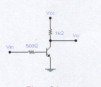
FIGURE 3.1
Connect 8-1 digital decoder to the Base of eight numbers of BJT npn transistors and connecting their Vcc to the eight analogue signals. The output form the BJT's are connected to gather with eight diodes to restrict any feed-back voltages. as shown in the figure:
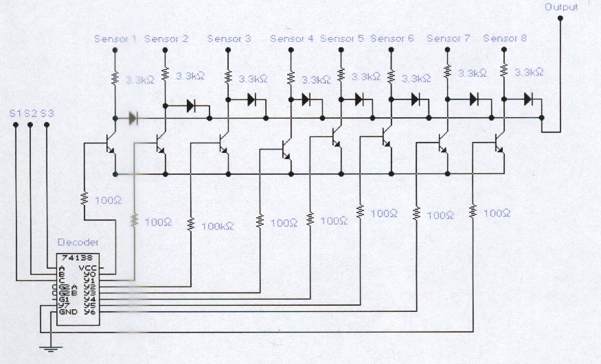
FIGURE 3.2
The 8-1 Decoder is connected to the 3-bit digital counter. as per the following truth table.
| S0 | S1 | S2 | O0 | O1 | O2 | O3 | O4 | O5 | O6 | O7 |
| 0 | 0 | 0 | 0 | 1 | 1 | 1 | 1 | 1 | 1 | 1 |
| 0 | 0 | 1 | 1 | 0 | 1 | 1 | 1 | 1 | 1 | 1 |
| 0 | 1 | 0 | 1 | 1 | 0 | 1 | 1 | 1 | 1 | 1 |
| 0 | 1 | 1 | 1 | 1 | 1 | 0 | 1 | 1 | 1 | 1 |
| 1 | 0 | 0 | 1 | 1 | 1 | 1 | 0 | 1 | 1 | 1 |
| 1 | 0 | 1 | 1 | 1 | 1 | 1 | 1 | 0 | 1 | 1 |
| 1 | 1 | 0 | 1 | 1 | 1 | 1 | 1 | 1 | 0 | 1 |
| 1 | 1 | 1 | 1 | 1 | 1 | 1 | 1 | 1 | 1 | 0 |
S0, S1, S2 are triggered by 3-bit counter which gets its pulses from computer parallel port pin#3.