
|
Remote Sensing and Control System (Graduation Project -2001) |
The function of an ADC is to convert an input analogue voltage into digital number. The digital number represents the input in discrete steps having a finite resolution is determined by number of bits in each digital word and it is equal to one part in 2^n. The ADC samples the analogue signal present at its input terminal at regular intervals for each sample.
There are many types of ADC:
|
1) Ramp ADC: In the start of the conversion the counter is cleared so it has zero count. the clock then makes the counter to go through its counting sequence. The out put of the counter is then applied to the input of the DAC and is counting sequence. the output of the counter is applied to the input of the DAC and is also made available at the output terminals. The DAC output is compared with the analogue input signal voltage. If the analogue input is equal to the DAC output then conversion stops. |
|
|
2) Tracking ADC: A much improved performance can be obtained at a very little cost if an up-down counter replaces the normal counter. |
|
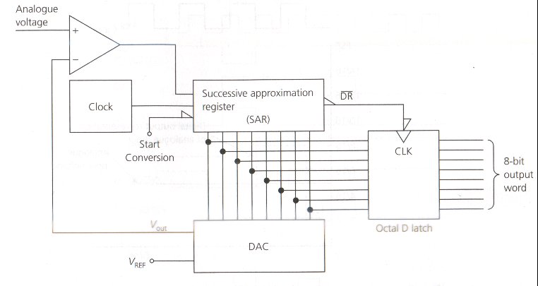
| 3) Successive Approximation ADC: The conversion technique that is applied in most of the ADC IC's is the Successive approximation. The circuit operates by comparing the analogue signal voltage with number of approximate voltages, which generated at the DAC output. |
|
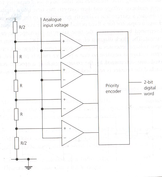
| 4) Flash ADC: A reference voltage whose value is equal to full-scale analogue input voltage is applied across voltage driver the consists of 2^n + 1 resistors connected in series. The driver splits the analogue voltages into 2^n - 1 parts. The value of the voltage is determined by highest voltage comparator to have a high output. All comparator outputs are connected to the priority encoders. |
|
| 5) Integrating ADC: It is the time taken by the capacitor to charge to determine the input analogue voltage and then converts this time into digital word. |
|
Using ADC0803 for Digitization:
The ADC080x series of A/D converters operate on the successive approximation principle. Analogue switches are closed sequentially by successive approximation logic until the analogue differential input voltage matches a voltage derived from a tapped resistor string across the reference voltage. The most significant bit is tested first and after 8 comparisons (64 clocks), an 8bit code (11111111 = full scale) is transferred to the output latch.
For further information on applications and functionality of ADC0803 refer to the DATA SHEET -- (ADC0803.pdf)