

|
Remote Sensing and Control System (Graduation Project -2001) |
5- Computer Interface Programming
An Interface is some kind of hardware or software that is used to connect two electronic devices or systems to enable them to communicate. control systems often need interfaces between computer and the controlled devices, especially if the distance between them and the size of the data is large then the data is converted from one form to another. If a device that has 30 bits of data, it is not practical to have 30 data to connect to the computer if the distance is also large. The data is therefore converted from parallel to serial form to reduce the number of data lines being used.
Parallel Port Interfacing:
To make this project simple, we would study how can we interface our system with the computer using a parallel port. IBM compatible PC defines the printer port as the parallel port commonly known as DB-25S following TTL logic standard for voltage inputs and outputs. IBM BIOS defines 4 parallel port base addresses stored as 4 16-bit word starting at the main memory address 0x408, 0x3BC, 0x278. Register address with in the parallel printer port.
| Port | R/W | Bits | Functions |
| Data out | W | D0-D7 | 8 LS TTL Output |
| Status In | R | S3-S7 | 5 LS TTL Output |
| Control out | W | C0-C3 | Internal IRQ Enable |
| Control out | W | C4 | Internal Tri-state Data |
| Control out | W | C5 | Internal Tri-state Data |
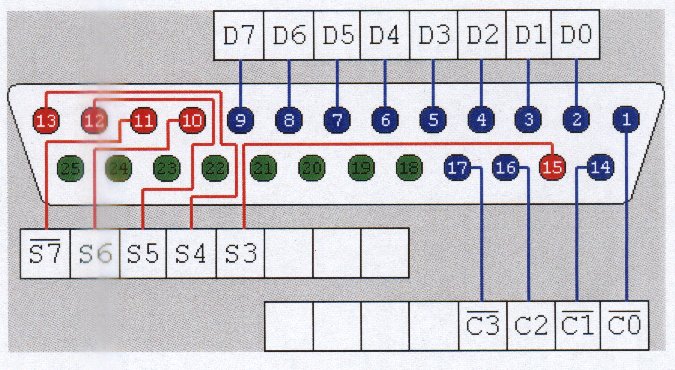
Figure 5.2
A 74LS374 octal Latch originally drives the data output pin, which could source 2.6mA and sink 24mA. There are 0.0022µF capacitors between each line and ground to reduce transients. It is essential that the external device not try to pull these lines to the ground, as this might cause the 74LS374 to source more current than it could handle without damage. The new feature is bidirectional support. That is when C5 is set to 1the data-out port is tri-stated and data can be read by the feed back register.
Any pin which is pull extremely low via TTL or switches will probably read low in the data feedback register, because TTL low (sink currents) tend to be higher than the (source currents) TTL high. This is not recommended because it stresses the 74LS374 beyond the safe margins and could cause chip failure. This means that if we are using external supply then for safety reasons we could use data out pins to sink up 24mA from +5V supply or Use buffer ICs. AND and OR gates make good buffer ICs. They are cheap and easy to use.
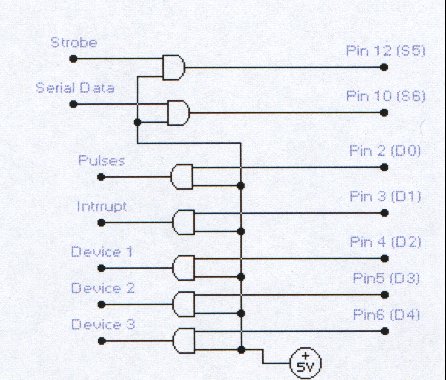
Figure 5.3
Hardware Programming:
It means that we can control external electronic device or get a feed back status of a device by writing a small software. We can access different parts of the computer by such programming. A very powerful hardware language is IBM assembly language. All codes are written directly in code language. Following are some of the 16-bit registers:
Each register is divided into two 8-bit registers AX has AL and AH registers. Let us examine a sample code in machine language embedded in simple Visual Pascal (Delphi) compiler. This program is to change the status of a single device connected at port 378h, without changing the status of any other connected device.
| > asm | Begin assembly language code |
| > mov DX, 378h | Store port address in DX register |
| > in AL, DX | Check input at DX port and store in AL |
| > and AL, 11111011b | And AL register and store the value in AL |
| > out DX, AL | Send an output to the port in DX, the value stored in AL |
| > end; | End of assembly language code. |
Programming Algorithm:
The program should not only be consisting of hardware language but it should be user friendly too. The project software was designed using an advance form object oriented Pascal known to be Borland Delphi. Before we start to program we need to know how our programs will run and what are their control limitations. This becomes very clear while charting a flow diagram. [ Software Algorithm Flow Diagram ]
Here are some points which will help to determine the functionality of the software and communication code with DAC (Data aquisition system).
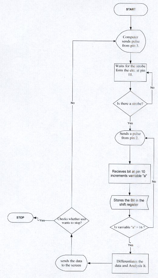
Figure 5.4