3 December 1998. The compression of the pictures
on these pages is optimised for detail rather than minimum download time
!
|
The Schebler model "H" carburettor
was standard equipment on the HD "F" and "J" models
|
I.
Introduction
The Schebler
model "H" carburettor was one of the first so-called "automatic carburettors",
allowing single cable control, for motorcycles. It was an immediate success
and was used on many American motorcycles as standard equipment in the
period from 1908 to 1926. It is a well designed and built instrument with
a bronze body and float-bowl but, because of its many moving parts, it
is prone to wear which is the main reason why this type of carburettor
sometimes cannot be adjusted to work properly leading to its "love or hate
it" reputation. Although even when using a worn model "H" carburettor the
motor cycle engine might still run quite well on the road, in particular
problems encountered in starting the engine, erratic idling and excessive
fuel consumption are clear signs of a "tired" Schebler carburettor. For
example on a 1916 Harley Davidson 1000cc model "F", fuel consumption with
a worn carburettor may be as poor as 10 km to the litre of petrol whereas
the consumption is normally about 15 km to the litre !
The operation of the Schebler model "H" carburettor
is very well explained in the 1928 Schebler "Motorcycle service station
manual", reprints of which are available from Mr. J.W. Boon, Meppelerweg
3, NL-7963 RV Ruinen, Netherlands (telephone NL (0) 522 471 177). This
booklet also gives extensive instructions on how to repair and adjust the
model "H" carburettor as well as details about other Schebler carburettors.
It really is indispensable as a source of reference. In fact, most of the
drawings used in this article are taken from this manual. However, in spite
of the well-presented information in the manual it is not so easy to apply
its teaching in practice because none of the spare parts or special tools
referred to are available nowadays. Much improvisation is thus necessary
to obtain the best results for a rebuild to the original specification.
The experience acquired when restoring three Schebler "H" model carburettors
from scratch led to the following comments and tips, which the author hopes
will be of special help when rebuilding a Schebler "H" model carburettor
so that no serious and reasonably competent motorcycle enthusiast need
be afraid of such a restoration. Although none of the special tools referred
to in the manual are necessary for the restoration, a small lathe is indispensable
for the repair of many parts and some taps and dies in USS sizes might
be necessary.
All the parts of the model "H" Schebler carburettor
and the respective references to the parts are shown on the next two pages.
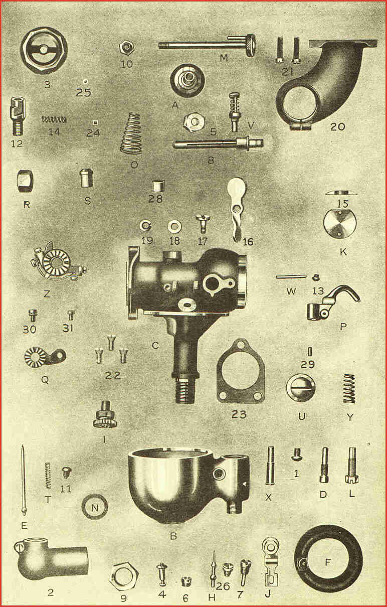
List of parts Model "H" Schebler Carburettor

        Symbol      Name
         A      Leather air valve disc with Monel bushing (replace the leather by "Teflon")
         B      Bowl casting
         C      Body casting
         D      Spray nozzle
         E      Needle valve
         F      Cork float (replace by brass float)
         H      Float valve
         I      Needle valve adjusting knurl complete
         J      Float lever
         K      Throttle disc
         L      Low speed adjusting screw
         M      Air valve starting stem complete
         N      Cork gasket for bowl or bowl cap (replace by "O"-ring)
         O      Air valve spring
         P      Needle valve lift lever complete with knurl "I"
         Q      Throttle lever  (can be straight instead of curved)
         R      Gasoline union nut
         S      Gasoline union nipple
         T      Needle valve spring
         U      Bowl cap
         V      Flusher
         W      Needle valve lift lever pin
         X      Needle valve guide
         Y      Needle valve lift lever spring
         Z      Cam complete (new style cam)
         1      Low speed lock screw
         2      Air bend (for Indian, Harley Davidson has a different type)
         3      Air valve casting
         4      Float washer and screw
         5      Throttle lever lock nut
         6      Float valve retainer nut
         7      Float lever screw
         8      Throttle shaft without Monel bushing
         8A     Throttle shaft with Monel bushing for bushed body
         9      Bowl lock nut
        10      Air valve spring retainer nut
        11      Needle valve lock screw
        12      Air valve adjusting screw
        13      Lift lever pin lock screw
        14      Air valve adjusting screw friction pin
        15      Throttle disc friction washer
        16      High speed auxiliary air valve
        17      Pivot screw for high speed auxiliary air valve
        18      Washer for pivot screw
        19      Lock washer for pivot screw
        20      Manifold (for HD sports model)
        21      (2) Manifold clamp screws (each)
        22      (3) Manifold cap screws (each)
        23      Manifold gasket
        24      Air valve adjusting screw friction fibre
        25      Air valve adjusting screw friction ball
        26      Float lever pin bearing
        28      Monel bushing for body (bronze or brass is O.K.)
        29      Lift lever fibre
        30      Adjusting screw (high or low speed) for cam track
        31      Lock screw for track adjusting screw
        32      Cam tracks (not illustrated)
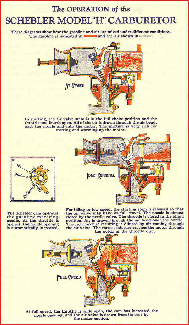
II. Operation
and constructional details
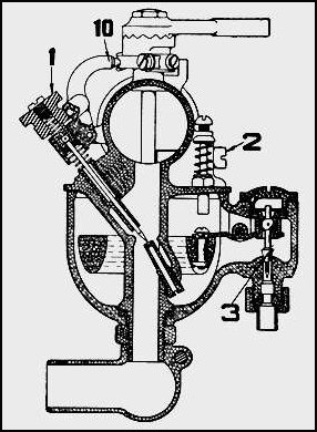
For the
operation of the Schebler model "H" carburettor reference is made to the
attached drawings in which the starting, idling or low speed and the high
speed conditions are explained. The carburettor has a large air passage
(secondary air passage) which is closed by a spring biased valve and an
open smaller air passage (main air passage) in which a fuel metering valve
is positioned. In operation, rich mixture coming from the main passage
is mixed with air coming from the secondary air passage to give the required
mixture strength. Mixture strength thus primarily depends upon the air
flow resistance past the air valve and the fuel metering valve setting.
The fuel-metering valve is in the form of a needle valve the needle part
of which is actuated by means of a needle valve lift lever (P in Figure
1). The upper end of the lever runs on an adjustable cam track in the form
of a strip adjustably mounted to the throttle shaft, so that when the throttle
shaft rotates the cam surface slides under the lever end for actuating
the lever in accordance with the cam track settings. Because of the very
small movements involved for the fuel metering flow adjustments, even small
amounts of wear in the respective parts have a large effect on fuel metering
and therefore particular attention has to be paid to the actuation of the
needle valve in order to ensure play free control. Thus, both the air-valve
and fuel metering valve are vital parts of the carburettor and the highest
degree of restoration accuracy is needed here.
III.
Restoration
When taking
the carburettor apart, first check with the help of the above Figure 1
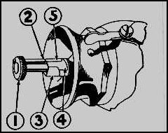
whether all parts are original. Two different types of cam lever arrangements
exist which are depicted below.
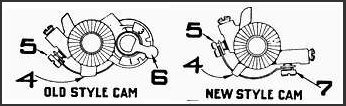
Instead of two screws for adjustment of the cam
track curvature the old style cam arrangement uses one screw and a rotatable
pointer. The needle valve lifting lever of the old style cam arrangement
has a small rotatable wheel, instead of a fibre point that runs on the
cam track. It is advised to convert the rotatable wheel of the older type
of lift lever to become a fixed wheel. Such a wheel can be manufactured
from polytetrafluoroethene (PTFE, better known under the trade name "TEFLON")
and is fixed to the lever to slide over the cam surface. In that way play
between the lever arm and the cam surface is effectively avoided.
*Air valve
Let us start with the air-valve which, under running
conditions, is constantly moving on the air valve stem M and therefore
normally considerable wear can be expected here. A leaking air valve is
often the cause of bad starting due to the fact that sufficient vacuum
cannot be developed to draw enough air through the main air passage.
In order to check the concentricity and soundness
of the conical air valve seat of the air valve casting, a supporting spindle
should be manufactured on the lathe. Such a spindle having the same screw
thread as the air valve adjusting screw (or a larger screw thread if the
thread in the air valve casting is damaged) cut on one end is used to support
the casting in the lathe chuck so that accurate machining of the valve
seat can be ensured. If the original air valve adjusting screw is found
to be worn, the new threaded spindle part, cut to the right length, can
be used to make a new adjusting screw later. The valve itself is made of
leather which material can still be used by the purist. However, Teflon
is preferable because if the motorcycle is not regularly used - which is
true for most of the 1915 to 1926 period motorcycles - contact with petrol
makes the leather very dry and hard with the risk of warping so that again
problems may arise when trying to start the engine after longer periods
of rest. Teflon is the right material in this place because it is light,
not affected at all by petrol and it gives a durable sealing surface. The
air valve is mounted on a brass supporting bushing which should slide with
small but sufficient clearance over the shaft to allow undisturbed movement
even when the carburettor is hot. The spring O should give a spring force
of about 200 grammes (7 ounces) before opening the valve. Test the valve
by placing it over your mouth and breath. Inspiration should be almost
impossible, expiration almost unimpeded.
*The throttle shaft assembly
In most cases the throttle shaft is worn and should
be replaced because the slightest play on the throttle shaft influences
the needle actuation. Making a new throttle shaft is not an easy job, in
particular because of the accuracy required when machining the slit in
which the throttle disc is held. However, it was found that in most cases
the old shaft can be repaired in a very simple manner to function properly
for many years. Take out the old throttle shaft and ream the holes in the
body casting C so that they are round and fully in line again. Take the
Monel bushing off the throttle shaft (if there is one mounted) and clamp
the throttle shaft with its screw threaded end in the self cantering chuck
of the small lathe. Drill a centre point hole in the other end of the throttle
shaft which is then used to support this end of the shaft by the lathe
tail stock centre during machining of the worn bearing areas. Prepare small
brass bushes with their inner diameters adapted to the diameters of the
machined throttle shaft areas and mount these bushes on the throttle shaft.
Since the throttle shaft is quite fragile, due to the longitudinal slit,
it is advised to use a sliding fit and "Loctite", or a similar anaerobic
polymer, for the mounting. Now the outer diameter of the bushes can be
machined to the size of the respective holes in the body casting for a
perfect fit without play. This simple repair method proved very effective.
In particular the use of "Loctite" for the fixing of the bushes is very
satisfactory and in fact it is difficult to see any trace of repair after
machining of the old throttle shaft to become an oversize throttle shaft.
It is not necessary to use Monel as the bush material. Brass does a good
job here.
*Throttle disc, friction washer and
low speed screw
In most cases the throttle disc can be reused. However,
carefully check the throttle disc friction washer 15 for wear because this
part ensures the sealing of the disc assembly, which is a prerequisite
for exact idling-adjustment of the carburettor. Be sure that the throttle
disc and friction washer perfectly close the throttle opening by looking
through the body towards the light. At places where small openings at the
circumference of the disc can be seen the disc can be flattened out slightly
with a hammer and should be filed to the right shape. With the low speed
adjusting screw in place no opening must show around the low speed screw
and yet the disc must not bind. When satisfied with the closing abilities
of the disc use some soft solder for fixing the disc to the throttle shaft.
*Cam assembly
It is advised to replace the cam track to ensure
a new smooth cam surface. A new track can be made of a small strip of stainless
steel which is held in place by small shoulders on the support in the middle
of the cam strip (see drawings of the old and new style cams). Carefully
check whether the track is mounted such that a progressive opening of the
needle valve is guaranteed. Use a micrometer to check the gradual change
of lift of the lift lever. Take your time to bend the strip so that gradual
change can be guaranteed at different settings of the screw and pointer
adjustments.
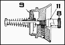
*Lift lever, adjusting knurl and needle
valve
The following drawing shows the position of the parts
referred to.
It is emphasised in the Schebler 1928 manual that
it is inadvisable to put in a new spray nozzle unless it is really necessary,
which case in fact is extremely rare. However, in contrast to what is stated
in this manual, replacement of the needle valve is more often required
because this is the part that is continually moved and therefore most likely
to wear and also because it usually is mistreated. Carefully examine the
needle to be sure that it is perfectly true. It is also important that
the needle slides with virtually no play in the needle valve guide X, so
that control of the needle is a perfect up- and down movement without any
swivelling or sideward motion. Needles were sold in slightly varying lengths
to cope with the manufacturing tolerances and therefore the length of the
original needle should be carefully measured before manufacturing a new
one. In fact it is advised to make a set of say 5 or 6 needles with slightly
different lengths and slightly different point shapes, so that after some
experimenting the most satisfactory needle can be selected. The original
needles are made of brass and have a ball joint formed at one end for allowing
the transfer of the swivelling movement of the lever arm into an up- and
down movement of the needle. Such needles are not easy to manufacture from
shaft material but it was found that stainless steel pop rivet pins (the
pin or shaft that breaks when the rivet is set), which are readily available
in different lengths and shaft diameters, are ideal blanks to start from.
Because these pins are already provided with a ball shaped end, they thus
only need to be cut and ground to become a new needle ! Grinding should
preferably be done in a lathe so that concentricity can be ensured. The
conical point should be made at least as long as the conical point of the
original needle, preferably slightly longer because this gives better petrol
flow adjustment possibilities which can be controlled by means of the adjustable
cam. Check carefully also the lift lever for perfect functioning and replace
the lift lever swivelling pin by an oversize one in order to ensure perfect
swivelling movement without any side play.
*Float, float valve and seat
These parts also need careful attention, in particular
it should be checked whether the ball joint of the float valve has too
much clearance in the float lever assembly J. Often this is the case and
sometimes the float valve is not lifted from its seat even when the float
is in its lowest position! In particular when the tank is not full and
thus there is not much fuel pressure, the weight of the float valve needle
is sufficient to prevent petrol from flowing into the carburettor and so
as to prevent the engine from starting (On the road this fault does not
occur because engine vibrations keep the valve moving, therefore it kept
me busy for some time to find the true cause of the strange behaviour of
my 1916 Harley Davidson!). Again all swivelling points should be checked
and if necessary repaired to give perfect swivelling movement without side
play or binding. It might be necessary to use an oversize pin in the float
lever bearing caps 26, 7. The original float was made of cork, which material
is not fully satisfactory for motorcycles that are not used regularly.
It has a tendency to disintegrate even when shellacked, in particular when
using lead-free petrol, probably due to its higher benzene content. The
float has a toroidal form which is difficult to produce in the home workshop.
Luckily, a very valuable tip was given in the "Classic Motorcycle" magazine,
issue of July 1994, page 47. A reader found that a brass float (part nr
293477) from a Briggs and Stratton stationary engine could be fitted in
the Schebler carburettor! It is very easy to install because it can simply
be soldered to the brass float lever J, after removal of the soldered float
pivot on the brass float. This Briggs and Stratton brass float (made in
Milwaukee!) is perfect for the 1" type of Schebler "H" model but it is
not known if it is also suitable for the 3/4" and 1 1/4" types so try it
out yourself; the brass float cost only about ten Deutschmarks in Germany.
According to the Schebler manual the float height with a cork float should
be measured from the top of the float to the top of the bowl when the float
valve is seated and the float is exactly level. Values of 19/32" and ½"
are given for the 3/4", 1" and 1 1/4" types, respectively. However these
values are no longer valid when using a brass float and even in case of
a cork float proved to be insufficiently accurate. It is better to find
the right position by trial and error. Assemble the carburettor and set
the float level such that up to about 60° inclination of the carburettor
no petrol leaks out of the spray nozzle (and thus also not through the
main air inlet when the motorcycle is held at this angle). Care is required
to ensure that the float does not touch the bowl or central portion in
the assembled state of the carburettor! When assembling the carburettor
be sure that a suitable "O" ring is place in the bottom of the bowl.
IV.
Mounting of the carburettor
Be sure
that the manifold gasket is in place and that the manifold connections
are made so that there are no air leaks. When the Schebler carburettor
is mounted in the "V" of a "V" engine such as is the case with the Harley
Davidson "F" and "J" models, it is advised to use a manifold gasket which
is thick enough to serve as a heat barrier. These older engines run very
hot and without such heat barrier the carburettor is easily heated by conduction
to the point where the petrol starts boiling. Such a manifold gasket can
be made of Teflon or other high temperature resistant material. The further
advantage of using a thick gasket is that the carburettor gets slightly
more clearance in the "V".
Originally the carburettor was fixed to the manifold
by means of three cap screws 22, which mounting is not very practical.
These short screws are easily lost when trying to insert them in the manifold
screw holes with one hand while using the other hand for holding the carburettor.
Because of their particular form and screw thread each lost screw has to
be manufactured yourself ! It is therefore advised to use small studs and
nuts for the mounting. Such conversion makes installing of the carburettor
much easier because it is now supported by the studs on the manifold and
the nuts can be held in a socket tool, avoiding the risk of losing them.
Manufacture of the studs (take stainless steel) is an easy job on the lathe
and needs no further explanation. The nuts should have a tapered or rounded-off
nose to fit into the manifold screw holes which are conical. Such nuts
can easily be manufactured when starting from readily available nickel
plated or stainless steel dome nuts, which are drilled through and a new
screw thread (use the thread of the nut or a bigger one) is cut.
V.
Instructions for adjusting the carburettor
The high
speed air valve on the side of the carburettor is used only when the engine
runs at extremely high speed and this valve should be kept closed when
adjusting the carburetor. The spring tension of the auxiliary air valve
can be increased by adjustment of the air valve adjusting screw, to tighten
the spring tension turn the button (1) to the left without pulling the
button out. To loosen the spring tension, turn the button to the right.
This button, when being pulled out and turned, can be put into three positions
on the air valve adjusting screw by means of the stem pin to control the
tension of the spring in accordance with starting (2), warming-up (3) and
normal running (5) positions. Under normal running conditions the pressure
of the valve should be 200 grammes (7 ounces) when the starting stem is
entirely released.
*Preliminary adjustments
Start with turning the needle valve knurl down as
far as it will go and make a mark on the knurl opposite the lift lever
arm for future reference purposes. Then turn the adjusting knurl roughly
three turns up.
*Starting of the engine
Pull out the knurled button on the air valve stem
and, by turning, place it in the choke position (2) in which the stem pin
is located on the extreme outward position on the air valve adjusting screw.
Start the engine with the throttle about one-third open. If necessary,
flood the bowl by means of the float depressor. After the engine starts,
the knurled button should be turned back in the intermediate position (3)
on the air valve adjusting screw so as to release the spring tension.
*Intermediate adjustment
Let the engine warm up and set the knurled button
on the air valve stem in its lowest position (5) on the air valve adjusting
screw. Open the throttle until the sliding point of the needle valve lift
lever rests at the position where the cam strip is supported on its supporting
casting. This part of the cam cannot be adjusted and serves as the reference
point. With the magneto fully advanced slowly screw the needle in or out
until the firing is quite even.
*Low speed adjustment
Close the throttle, keep the spark fully advanced
(in older manuals it is advised to retard the spark for this adjustment
but better results are obtained if the spark is kept advanced) and open
the low speed air adjusting screw about three turns. Then turn the low
speed cam adjusting screw until the mixture becomes so lean that the engine
backfires or misses. Then turn the low speed cam adjusting screw slowly
to the right until the engine runs smoothly. Adjust the engine speed with
the low speed air adjusting screw. Note that incorrectly set sparking plugs
points will often confuse the low speed adjustment.
*High speed adjustment
This adjustment should be done
on the road and involves real try and error. Try out different positions
of the pointer on the dial until the engine pulls best on full throttle.
If when the pointer is in position "3" mixture is still too lean, increase
the tension of the air valve spring by turning the air valve adjusting
screw to the left. If necessary repeat the foregoing adjustment steps and
make adjustments only when the engine has reached its proper working temperature.
VI.
Appendix
Normally
it takes some time to get acquainted with the carburettor adjustment procedure
and in the beginning it might appear quite difficult to arrive at a setting
at which the motor works well over its entire speed range. Two things are
indeed very important here. First be sure that there is no play in the
needle controlling parts and that the cam gives a progressive opening of
the needle valve and secondly keep strictly to the above sequence of adjusting
steps. Those who want still more information - or who perhaps have valuable
further tips on the restoration of the Schebler model "H" carburettor -
can contact me on the Internet E-mail address below. Wishing you luck with
the restoration and adjustment of your Schebler Model "H" carburettor and
many deserved happy miles on your motorcycle !
Copyright PRAVG

My E-Mail addresss
