updated 12 April 1999
| HD Gear-box and clutch
assembly |
Sealing
of an "F"-head Harley Davidson gear-box
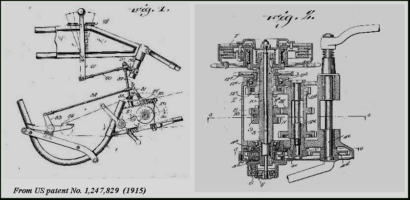
This is
a unique drawing of the later HD model "F" and "J" gearbox and clutch assembly.
The drawing is taken from the 1925 US patent No.1,549,976. It might take
long to download the file but the high resolution of the drawing allows
a print-out to DIN- A4 size so that all the details can be recognised by
the keen restorer. When rebuilding the gear box, bearing 34 should be replaced
by a normal single row double sealed ball bearing.
*Gear-box
construction
Details
of the initial construction of the "F"-head HD gear-box are clearly shown
in the figures 1and 2 taken from the United States Patent No. 1247829,
relating to a specification filed by William Harley on 24 August 1915.
Later models of this gear-box included a kick starter (US patent No. 1184345)
and, in order to cope with the higher engine output, most of the ball-
and sleeve-bearings were replaced by roller bearings as well as that at
the end of 1919 the clutch bearing was simplified requiring a longer main-shaft
(see the above figure of the 1925 gear-box).
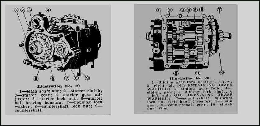
Other changes included the
use of oil retaining brass sealing washers (see illustrations 19 and 20,
taken from the Harley Davidson Rider's Handbook 1923) so that, instead
of the then usual high viscosity mixture of grease and oil for which no
special sealing was required, lubrication of the gear-box internals could
be improved by the use of oil only. The original sealing by brass sealing
washers was however prone to wear and thus required short service intervals
to keep the gear-box oil-tight.
*Modifications
During
restoration of such a gear-box it was realised that improved sealing and
longer life expectancy could be achieved with minor modifications which,
although relatively simple and cheap, necessitate the use of a lathe and
simple grinding equipment. In fact, only four openings in the housing,
those supporting the main- and counter-shafts, need to be sealed. One end
of the counter-shaft is held in the housing by a nut which presses this
end of the shaft against a steel bush in the housing; normally no leakage
occurs here so no modification is necessary. The other end is mounted as
a sliding fit in a steel bush, this allowing insertion of the counter-shaft
into the housing assembly. To prevent leakage, a small groove should be
ground in the end of the shaft to accommodate a suitable O-ring. Since
it is very difficult to start from a given O-ring size and then achieve
the correct groove size the groove was ground first and then an O-ring
was selected of a size ensuring tight sliding into the bush (see picture
1).
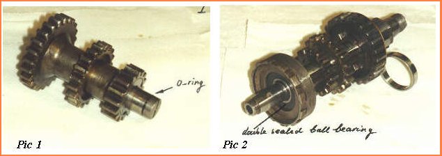
Sealing the main-shaft was slightly more complicated.
The main-shaft is supported on the drive side of the gear-box in a roller
bearing (on earlier models a ball-bearing was used) and on the kick-starter
side in a ball-bearing. The latter is supported in a hub, screw mounted
in the housing for axial adjustment of the main-shaft assembly to achieve
the required axial clearance (the main-shaft assembly is shown in picture
2).The roller bearing (33 in the first gear-box figure) is "inch-size"
but, strangely enough for an American bike, the ball-bearing (34) is millimetre
sized (52x20x15mm, in both the gear boxes I have restored). This single
row angular contact bearing can be easily replaced by a double sealed version
of a single row radial ball bearing (6304-2RS) of the same size, without
adversely affecting assembly of the gear-box or its life expectancy (see
picture 3).
An alternative for the roller bearing would be
very difficult to find so that the original races, which were in good condition,
were used again with new rollers. However, if necessary this bearing can
be replaced by the single row roller bearing assembly 40x80x18 (NU208ECP)
or 40x80x23 for the later gear boxes with larger width rollers (1925 to
1929). In that case an adapter sleeve should be manufactured to make up
for the difference in outer diameter between the bearing and recess.
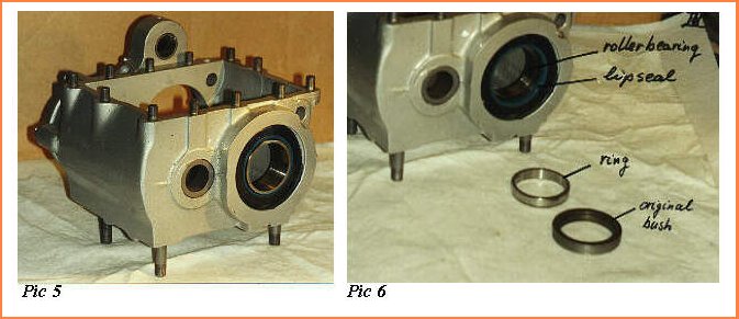
On the main-shaft, between the roller bearing
inner ring and the drive sprocket, a bush of the size 50.4x40x8.4mm (50.4x40x15.3mm
for the later boxes) was originally fitted; the width of this bush and
its diameter with respect to the housing were just sufficient to be replaced
by a sealing combination of ring and lip-seal.
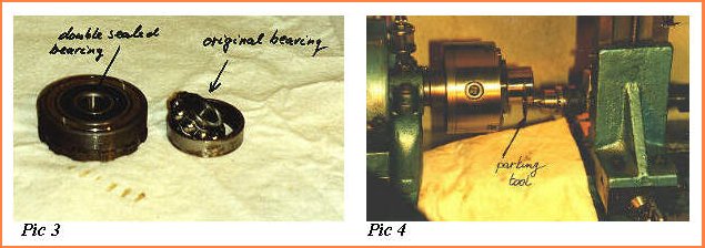
Since it is very important that this new ring be
accurately mounted on the shaft as well as being rigid and ground to provide
a precision contact surface with the lip-seal, a readily available roller-bearing
inner ring of the size 40x45x40mm (SKF) was chosen, and the required width
of 8.4mm (or 15.3mm for the later gear boxes) was obtained by parting off
on the lathe using a grinding disc (see picture 4). The parting disc was
supported on a shaft clamped to the tool support and was driven by a flexible
shaft and high speed motor for which I used a wood work routing motor.
In addition a lip-seal of the size 45x52x4mm was selected for the housing
whose bore is originally 2"= 50.8mm. It would of course have been possible
to rebore the housing to the required diameter of 52mm; however, this is
not an easy job and risks making the bore eccentric with respect to the
shaft. It was therefore decided to grind the rubber layer off the outside
diameter of the lip-seal since its steel supporting ring proved to be exactly
the required diameter for a perfect fit into the bore (see pictures 5 and
6).
Having assembled the gear-box, not forgetting to
seal all bushings and screwthreads using a heavy graphite compound intended
for sealing hot water fittings, the gear-box is now substantially leakproof
at very low cost and without originality being greatly affected.
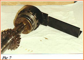
A tool for engaging the ball-bearing supporting
hub can be made from a pipe which just fits around the hub, the necessary
teeth being formed by bending portions of the circumference into the requisite
slots (see picture 7).
The same type of gear-box as described was used unchanged
far into the 1920's and even later boxes differ only slightly. Therefore
the suggested procedure may be applied to many other HD gear-boxes.If further
information is needed please write to the author.
Copyright PRAVG