[ Español ]
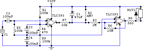
Circuit for symmetrical power supply:

Circuit for asymmetrical power supply:

Download these circuits for CircuitMaker 2000: snddet.zip
I wanted to replace a manual switch in an audio amplifier by an automatic system to switch it on and off depending on the presence of audio.
This is a design of my own. Connect an audio channel to the circuit input and the relay so it can disconnect the amplifier supplies. If it uses symmetrical supply a double pole relay must be used to switch both positive and negative rails.
This design is based on the LM393 dual comparator. The comparator on the left detects the presence of an audio signal and charges capacitor C1 and the comparator on the right activates the relay when capacitor C1 is charged.
LM393 comparator operation is as follows: it sinks almost no current through its inputs and can source up to 18 mA from each output. These outputs are open collector, that means the comparator outputs the negative rail when low and remains high impedance when high. This allows us to simplify the circuit further. When "+" input is set to a higher voltage than "−" input, the output is high impedance (high state) and when the opposite is true the comparator outputs the negative supply rail (low state).
In the schematics above the left comparator has a fixed voltage set on its "+" input through voltage divider R1, R4 and R9. C2 capacitor filters any noise (it does not work properly without it). With R4 set at its middle setting the voltage obtained is around 0.03V. Without an audio signal C3 blocks any DC component from the audio input and R5 ensures no voltage offset exists on "−" input, so voltage on "+" input is higher than voltage on "−" input thus the comparator output is high impedance and no current flows through R7. C1 remains discharged with 16V in its negative pin.
When an audio signal is input its alternating component goes through C3 and a voltage appears on "−" input. The positive swings will increase the voltage on "−" input above the voltage set on "+" input, causing the comparator to connect R7 to the negative rail for the duration of these swings. C1 will be charged though R7 and only if continued audio exists on the input it will charge enough to switch the comparator on the right and turn on the amplifier.
On the other hand, when an audio signal is no longer applied the comparator no longer provides a path through R7 to ground to charge the capacitor and it discharges slowly through R2. In one minute it will discharge to half the voltage. This delay keeps the amplifier turned on for a while after the audio source is removed.
The comparator on the right implements a switch with hysteresis to switch power to the relay depending on voltage on C1. Its "−" input is grounded (in symmetrical supply circuit) and the capacitor voltage connected to "+" input so when the capacitor is charged the comparator output will be a connection to negative rail (relay powered) and when the capacitor is discharged it will be high impedance (relay inactive). R2, R3 and R6 add hysteresis to the switch, without them it does not work properly (at the switch point the circuit oscillates and the relay produces a buzz). Resistor R6 provides some feedback from the output so when it switches the voltage applied on "+" input changes abruptly and stops any oscillation.
LM393 can be powered from 2V to 16V symmetrical (+/− 16V) or from 2V to 32V asymmetrical.
R8 resistor value must be calculated according to the supply voltage and relay being used. Most small relays switch properly with a voltage slightly below its rated voltage and is interesting to experiment with that to reduce its current draw. LM393 can source up to 18 mA, so if your relay takes less current you can drive it directly (as shown in the schematic). For larger currents you will need to add a transistor to switch power to the relay.
R8 resistor can be calculated with this formula. If not specified you will have to measure the relay current draw powered at its rated voltage.
Value (in ohm) = (supply voltage − relay voltage) / relay current draw (in amperes)
For the symmetrical power supply circuit you can double the voltage available to the relay connecting it to the positive supply rail instead of ground, this way you can power 18V, 24V or 32V relays. Don't forget to calculate the resistor properly.
It is important to note that the diode connected in parallel with the relay must be a fast switch type, for example BA157. Indicated polarity is correct, comparator output is negative supply rail. This diode protects the comparator from spikes generated by the relay coil when disconnected.
C1 capacitor is charged to rail to rail voltage (that is 16V + 16V = 32V), so use higher voltage rating.
LA6393 is equivalent to LM393.
R4 is a sensitivity setting, if you find the circuit too sensitive increase its value. If you find its range too large to adjust precisely you can replace the preset by a lower value one.
Project completed on July 2005.
Copyright © 2005 Jeroni Paul.