Page 2

Last update - September 21, 2002
| Borg Warner Velvet Drive Transmission Rebuild Page 2 |
|||||||||||||||||||||||||||||||||
|
|||||||||||||||||||||||||||||||||
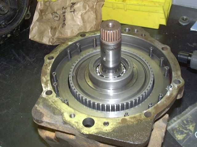
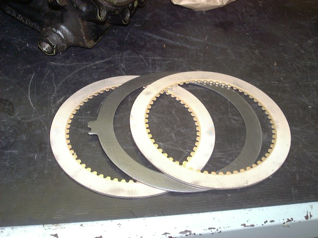
| To the left is the drivegear and forward clutch assembly inside the casing. There are 12 pressure plage springs used with the reverse clutch mechanism that have been positioned. The rear clutch and pressure plate are in the right picture. These are installed on top of the assembly in the left sided picture. | |||||||||||||||||||||||||||||||||
|
|||||||||||||||||||||||||||||||||
|
|
||||||||||||||||||||||||||||||||
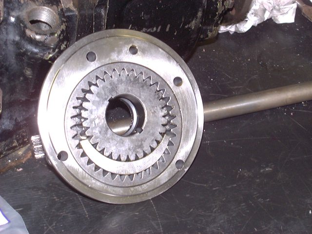
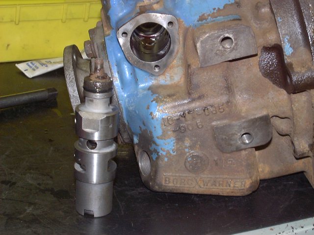
| After installing the rear clutch piston, I positioned the pump assemby on the unit. The pump itself is pictured to the right. The installed pump is visible in the image to the left. | |||||||||||||||||||||||||||||||||
|
|||||||||||||||||||||||||||||||||
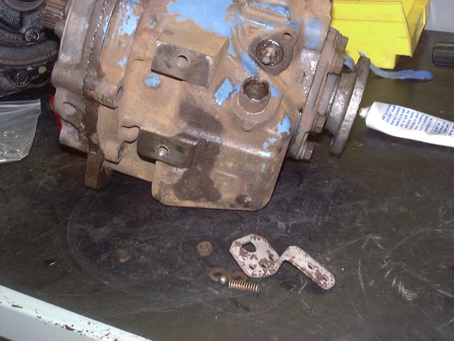
| The oil cooler return line is viewed here along with the strainer used to block large contaminants from circulating in the fluid. The rear coupling is also visible here. | |||||||||||||||||||||||||||||||||
|
|||||||||||||||||||||||||||||||||
| The control valve assembly is visible here and the location were it is installed is also visible. There was an O ring on this unit that was replaced otherwise no work was required on it. This unit has a large heavey spring inside it along with a regulator valve that is part of the forward and reverse fluid flow. | |||||||||||||||||||||||||||||||||
|
|||||||||||||||||||||||||||||||||
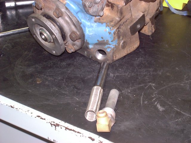
| The shift lever is pictured here along with the poppet spring and a 5/16" ball. This lever is connected to the control valve assembly after it is installed through the case (see image above to the left). | |||||||||||||||||||||||||||||||||
|
|||||||||||||||||||||||||||||||||
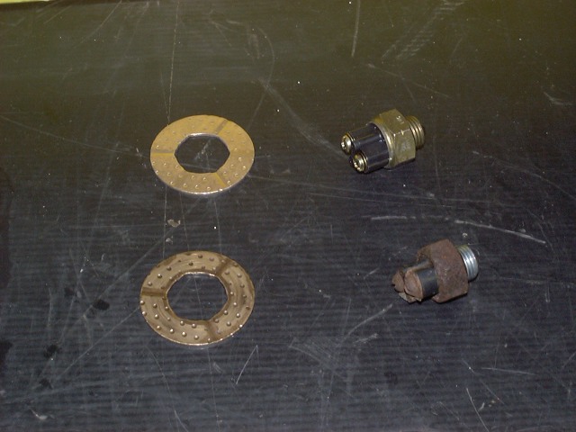
| This image should be included earlier on this page but here it is regardelss. The bronze ring here is a thrust washer. The NEW one is on the top and the used on is on the bottom. This thrust washer controls lateral movement of the planetary gear and the drivegear/fwd clutch assembly. The second item is the neutral safety switch. The new one on top and the badly corroded one on the bottom. | |||||||||||||||||||||||||||||||||
| More to come when this unit is reinstalled on the new engine..... Last update - September 21, 2002 |
|||||||||||||||||||||||||||||||||
| Tranny Page 1 | |||||||||||||||||||||||||||||||||
| HOME | |||||||||||||||||||||||||||||||||