Last update Sept 21, 2002
| Borg Warner Velvet Drive Transmission Rebuild | |||||||||||||||||||||||||||||||||||||||||||||
|
|||||||||||||||||||||||||||||||||||||||||||||
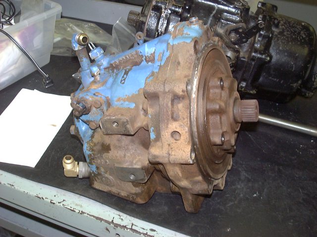
| Here is my 71C Borg Warner Velvet Drive Marine Transmission. The bellcover has been removed and I have cleaned off all the scale and loose paint. This page should detail the rebuild of this unit. | |||||||||||||||||||||||||||||||||||||||||||||
|
|||||||||||||||||||||||||||||||||||||||||||||
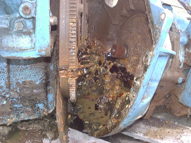
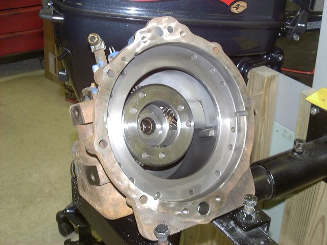
| Here is the first shot of the transmission. This is a shot inside the bellhousing just after I removed the tranny from the engine. Alot of marine growth was found inside. | |||||||||||||||||||||||||||||||||||||||||||||
|
|||||||||||||||||||||||||||||||||||||||||||||
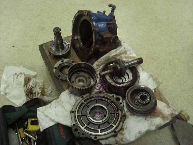
| Here are all the parts removed from the tranny. I will detail these parts as I clean and replace them in the case. | |||||||||||||||||||||||||||||||||||||||||||||
|
|||||||||||||||||||||||||||||||||||||||||||||
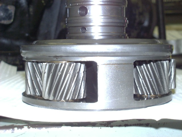
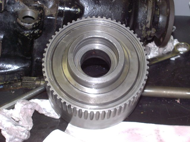
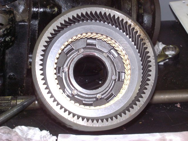
| Here is a shot of the planetary gear. The notches are to allow for oil flow. | |||||||||||||||||||||||||||||||||||||||||||||
|
|||||||||||||||||||||||||||||||||||||||||||||
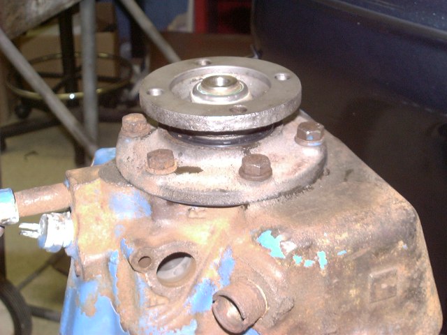
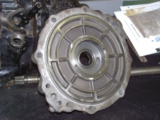
| The rebuild has started. Here is the main housing after I have replaced the rear main bearing, output shaft oil seal, rear cover, rear coupler and planetary gear. The rear coupler had to be pressed on and the output shaft nut had to be tightened to a torque between 100 & 200 lbs. An impact wrench was required since there was no way to hold the case while tightening the nut. | |||||||||||||||||||||||||||||||||||||||||||||
|
|||||||||||||||||||||||||||||||||||||||||||||
|
|||||||||||||||||||||||||||||||||||||||||||||
|
|||||||||||||||||||||||||||||||||||||||||||||
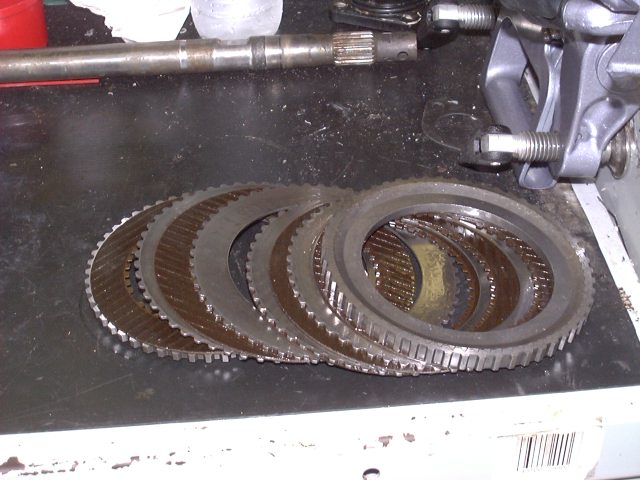
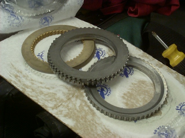
| Here are the foward clutches (clutch pack) and pressure plates. The new ones on the right, (clutch plates along with the steel pressure plates). The old clutches and press. plates on the left. | |||||||||||||||||||||||||||||||||||||||||||||
|
|
||||||||||||||||||||||||||||||||||||||||||||
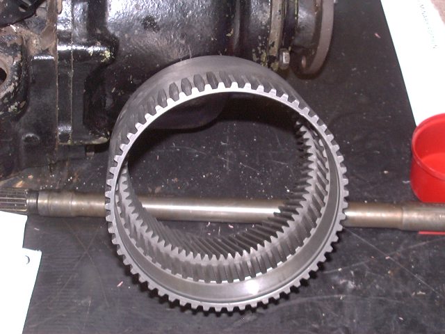
| The ring gear is pictured on the left. I have installed the new clutch pack in the image of the ring gear on the right. | |||||||||||||||||||||||||||||||||||||||||||||
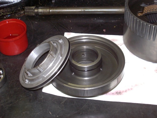
| The foward cluch piston and cylinder is pictured to the left. The aluminum piston has been removed so the seals can be replaced. The ONLY way to remove the piston from the cylinder is with compressed air. After the new seals were installed and the piston pressed back into the cylinder by hand, the entire unit was pressed (on a arbor press) into the ring gear-clutch pack assembly. A large snap ring is used to secure this unit in the ring gear. | |||||||||||||||||||||||||||||||||||||||||||||
|
|||||||||||||||||||||||||||||||||||||||||||||
|
|||||||||||||||||||||||||||||||||||||||||||||
|
|||||||||||||||||||||||||||||||||||||||||||||
| More to come........... Last update Sept 21, 2002 |
|||||||||||||||||||||||||||||||||||||||||||||
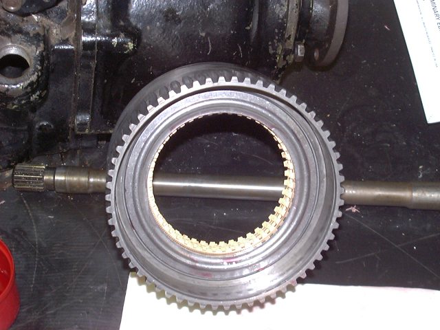
| Here is a reverse shot of the ring gear-clutch pack assembly. The clutch pack and the forward clutch piston assy. can be seen. | |||||||||||||||||||||||||||||||||||||||||||||
| HOME | |||||||||||||||||||||||||||||||||||||||||||||
| Here is a picture of the rear clutch piston assembly. It is very similar to the fwd piston but much larger. I replaced the seals and reinstalled the piston. Again, compressed air had to be used to remove the piston from the cylinder. I also replaced the needle bearing visible in this image. An arbor press was required for this procedure. | |||||||||||||||||||||||||||||||||||||||||||||
|
|||||||||||||||||||||||||||||||||||||||||||||
| Tranny Page 2 | |||||||||||||||||||||||||||||||||||||||||||||