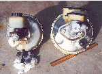
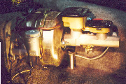
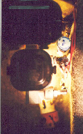
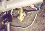
In the first image you can see that he relocated the booster vacuum line closer to the fender, thru a new hole. In the next (blurry) image you can see he also tucked up his �custom� distribution block between the master and the fender, and even fitted a proportioning valve in the rear brake line, by tapping into a 90 degree AN fitting, as seen in the last image. Jack reported that his master cylinder didn�t arrive with the fittings that thread into the master and begin the brake lines, however these fittings were included with my package. Without them, Jack found his own fittings, then tapped them (repeatedly � deeper each time) until the 90 degree fitting pointed just where he needed it to point. Then he plumbed the distribution block, and tapped the hole for the stock brake pressure switch, and installed the proportioning valve. He now reports the valve is set to �No Bias�, either with his Wilwood calipers, or his back-up stock set of calipers.
Once I had the master/booster assembly fitted in place, I went about locating the parts necessary to run the hydraulic lines. Even in my urban area, this took visiting numerous shops to locate all the necessary fittings.
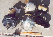
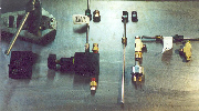
Plumbing the new system is generally straightforward, if you have done this kind of thing before (which I had not), have the right tools (which Jack loaned me), and take your time. Once the collection of fittings, tubes, components, and tools were acquired, I began assembly. Starting on the upper left, you see the flaring tool, and below that the adapters necessary to make �double flares�. It is important to note that the stock system consists of �Euro� fittings, which use �bubble� flares compared to the SAE fittings (double flare) used by the USA components. What I had to do was cut off the old fittings where the brake lines arrive under the master cylinder, and affix double flare fittings to the old and new lines.
Moving to the right, next you see the rear brake lines and Wilwood proportioning valve, and further over the front lines, brake pressure switch, and the �T�s necessary. |