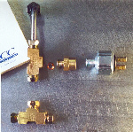
| What I did to reduce the number of flares I had to make was to buy several short brake line adapters from the local parts store. They came already flared with a fitting on both ends. I cut the line to length, using one original flare and creating the other flare myself. Dealing with the brake pressure switch could be a LONG story itself. Apparently, this switch is not in a SAE, or Metric size. Many people get by with just threading in what they have, but an engineer at Sunnyvale Valve and Fitting determined that this part, which threads into the Ford (European Capri) distribution block is none other than in �BSL�, which may stand for British Standard �Lame�. (No offense to the Brits, I just didn�t expect such a unique thread pattern.) It is sized very close to .375 (17/44 ???) 24 threads to the inch, fine thread, with a slight taper. My unit appears �stock�, so I exclaimed WTFO ? (What The *Fun*, Over ! for you non-pilots.) I found a very common NPT 3/8� thread pattern (no size adapter is necessary) brake pressure switch with the same pressure rating as stock (60PSI->120PSI), but with bullet connectors versus spade connectors. This challenge had been resolved ! Starting at the master end of things, I bent the brake lines (around a screwdriver handle), cut to length, and flared the ends as necessary. After some practice on some spare line, the flaring task went reasonably well. I did have a couple of �redos�, and the tool was a bit too large for the space available, causing some consternation. |
 |
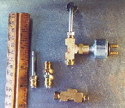 |
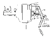
| In the middle image above, I learned that there are some limitations to how short one can make a connector line. The very short line with two fittings is just the right length. However the flaring tool needed a line long enough to grab on to, the minimum length turned out to be about two inches. |
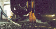 |
| There is not much space to work with, as you can see here it is about 1�, so the 90 degree bend in the brake lines connected to the master must be made rather sharp. |
 |
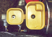 |
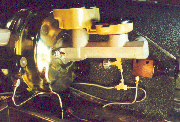
| The final result is shown above. I did drill a new hole for the rear brake lines to pass thru the floor of the trunk. Looking down at the reservoirs, you can see a black object in the rear portal. This is a pressure lock valve, which maintains pressure of about 2 pounds. This is similar to the blue external components seen spliced in the brake lines in several of the images above. Whether this is necessary for a stock brake system, I don�t know. There are a couple of adjustments that are necessary, now that the master/booster assembly is installed. First the pedal should be adjusted. |
 |
| The pedal height is set by adjusting the length of the shaft between the pedal and the booster on the inside of the firewall. If you retain the stock booster, and add just a new master cylinder, you may think you are finished. But there is one more adjustment to verify. |
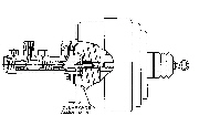 |
| The shaft between the booster and the master is adjustable. If the shaft is too long, then it will keep the master cylinder piston too far forward when it should be �at rest�. It may not retract far enough to feed the piston with brake fluid, and the position of the piston may still apply some braking force to the calipers. |
| Finally I bled the system, using SpeedBleeders mounted in each caliper. This made the task a quick one-person job. I highly recommend these components. I�d like to take a moment to thank everyone that helped by answering my questions, and offering advice. PrecisionProFormance has even offered to swap my new 1�stepped bore brake master with a larger bore master that is better matched to the Wilwood system for FREE ! So I insert this shameless plug for them here: www.precisionproformance.com. They were helpful, delivered the right parts, and quickly. Give them a call. Just when I thought I was done, and ready to take the car around the block, naked as it is, I learned the clutch master had similarly failed ! Lovely ! So now I am off on another adventure. The test drive of the new brakes will just have to wait. Stay tuned ! |
| ... |