Standard Terminal Arrival Procedures (STARs)
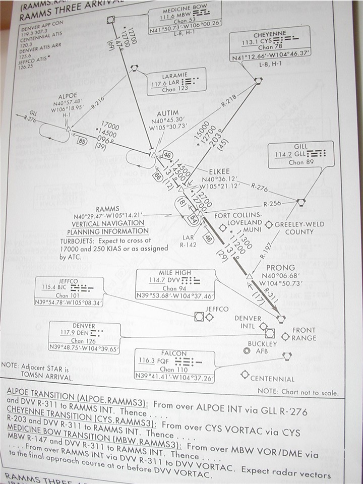
This is a photo of the Ramms 3 arrival into Denver International Airport. STARs are used at busy airfields to aid in traffic flow. STARs are usually NOT found at non-busy airfields, because they require the routings to be TERPS'd, that is, surveyed to ensure obstacle clearances and NAVAID reception, and that costs tax dollars to do so.
Aircraft flying a STAR must either be vectored onto the STAR (Air Traffic Controllers give the aircrew directions to intercept part of the STAR), or the aircrew starts the STAR from a pre-specified point, known as a transition. There are three ways to join the Ramms 3 arrival via a transition. The crew can file their route to the ALPOE intersection, the Medicine Bow VOR/DME, or the Cheyenne VORTAC. They then fly to the start of the STAR, which is the RAMMS intersection, and the STAR then ends at the Mile High VORTAC, near the bottom of the page. At that point, the controllers will vector the aircraft to final approach.
At the bottom of the graphical depiction, is the written instructions. To follow the instructions, the aircrew must start with whatever transition they filed, and then skip to the bottom to the remainder of the STAR. For example, if the crew filed the Medicine Bow transition, it reads: "From over MBW (Medicine Bow) VOR/DME via MBW R-147 (147 radial) and DVV (Mile High) R-311 to RAMMS int. Thence...from over RAMMS int (intersection) via DVV R-311 to DVV VORTAC. Expect radar vectors to the final approach course at or before the DVV VORTAC."
The STAR has a code which is placed on the flight plan routing to tell ATC that the aircrew has filed the STAR. If the aircrew are planning only to fly the STAR with no transition, they file RAMMS.RAMMS3. If they file a transition, they file the transition identifier plus the RAMMS3 (e.g. Cheyenne (CYS) transition: CYS.RAMMS3).
Several holding patterns are depicted, with holding fixes located at ALPOE, AUTIM and RAMMS intersections. Mileage depictions, as well as NAVAID information is the same standard used on high altitude charts (see previous page). The numbers above the middle of each route segment are called Minimum Enroute Altitudes (MEAs), and are designed to provide obstacle clearance as well as NAVAID reception.
Standard Instrument Departure procedures (SIDs)
A SID is the opposite of a STAR. Just as ATC controllers need STARs to ensure traffic flow into an airport, they use SIDs to manage traffic out of an airport. A SID is one of several methods an aircraft can depart an airfield on an IFR (Instrument Flight Rules) clearance. The first is a diverse departure, where the aircrew's clearance is "cleared as filed". Upon reaching 400 feet above ground level and past the departure end of the runway, the aircrew can turn direct to the first point on their flight plan route. The second type of departure is a Departure Procedure (DP). DPs are textual procedures printed in the front of an instrument approach procedure book, and are included in the non-standard departures section. An example of a DP might read "fly runway heading until 2000, then turn on course, maintain 5,000 feet". The next way to depart IFR is a radar vector departure. The aircrew is told on takeoff clearance to fly a certain direction. An example is "Josa 759, upon departure fly heading three six zero, wind zero five zero at ten, cleared for takeoff on runway one zero". Once the crew reaches 400 feet, they immediately turn to the assigned heading. From there, the controller vectors the aircrew as needed, and then clears them to fly their planned route after the controller no longer needs to vector them.
Finally we get to SIDs, the last type of departure procedure. These are graphical departure procedures, and the aircrew is given the SID in it's initial clearance prior to taxi. The aircrew is expected to fly the SID as depicted unless otherwise instructed. Usually it is rare for a crew to have to fly an entire SID. Many times, after the aircraft gets clear of the airport airspace, the controller will clear the aircraft off of the SID, and allow it to proceed direct to the next point on the flight plan.
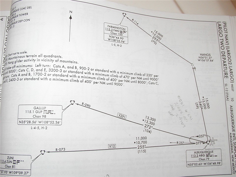
The above photo shows a picture of the Largo 2 departure from Albuquerque International/Kirtland Air Force Base. Not shown is the textual instructions on the next page (off the photo to the left), and is in the same format as the STAR above. Shown on the page are the non-standard climb gradients for each runway. The standard climb gradient for any aircraft is 200 feet per nautical mile. This can be reduced to as little as 152 feet per nautical mile on a single engine. Sometimes, obstacles prevent an aircraft from climbing at 200 ft/nm, and a higher climb gradient is required. In this instance, the mountains around Albuquerque requires a higher climb gradient. For Runway 8 (pointed right at the Sandia Mountain range), the climb gradient is 220 ft/nm for slower aircraft (categories refer to the aircraft's minimum speed), and 470 ft/nm for faster aircraft. Also listed are "see and avoid" minimums, which are weather minimums that can be used in lieu of flying the climb gradient. For example, for Runway 8, the see and avoid minimums for fast aircraft (Category C, D and E) is 3200-3, or 3,200 foot cloud ceilings and 3 miles of visibility. In this case, the aircraft can keep the obstacle in visual sight in lieu of climbing over it. NOTE: USAF and USN aircraft are prohibited from using see and avoid criteria, and MUST use the published climb gradient.
Once the aircraft reaches the end of the SID transition it filed, it then continues along its planned flight route. For example, if an aircraft was flying to Los Angeles, the crew would likely file for the Zuni transition. Once the aircraft reaches the Zuni VORTAC, it continues along its route to L.A.
Filing procedures for SIDs are the same as for STARs. Pilots will note the SID indentifier, in this case, LARGO2.LARGO...note, the terminology is reversed, because this is a departure. The SID name is first, THEN the transition, whereas on STARs it was the opposite.
Low Altitude Instrument Approach Procedures (IAPs)
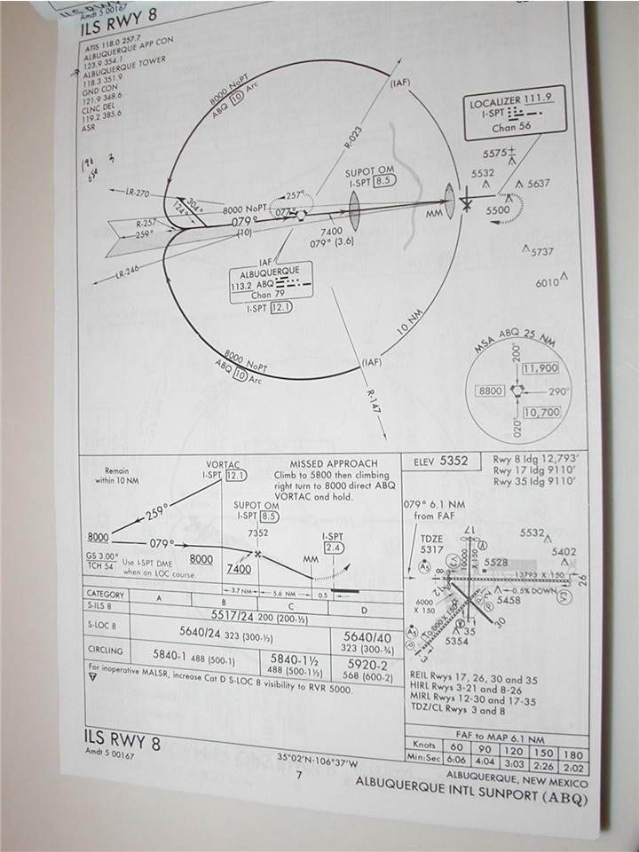
Instrument Approach Procedures are used to guide aircraft to the runway when the ground is obscured by cloud cover. On foggy days, or when the clouds prohibit a VMC (Visual Meterological Conditions) descent from an enroute altitude, the aircrew must rely on the airplane's navigational instruments to guide it to the airport and to the runway. There are several types of instruments, and each is defined by the type of NAVAID it uses. Shown here is the ILS (Instrument Landing System) at Albuquerque/Kirtland AFB. There are also VOR approaches, NDB approaches as well, but I will not go into detail with those types. See the previous page for a description of a VOR and an NDB.
There are two major types of approaches: precision approaches and non-precision approaches. Non-precision approaches provides azimuth (directional) guidance only. Minimum altitudes for various segments of the approach are listed, and the aircraft can descend to those minimum altitudes when it reaches the appropriate segment of the approach. Precision approaches, however, provide both azimuth and glidepath guidance. This glidepath guidance is vertical guidance. The indicators on the instruments in the aircraft keep the aircraft on a constant descent path to the runway, while the azimuth portion keeps it properly aligned with the runway.
The ILS uses a localizer signal. The localizer is a very concentrated, very sensitive radio beam that the aircraft's instruments lock onto. It keeps the aircraft very close to the extended centerline of the runway, and thus keeps it accurately lined up on final approach. Paired to the localizer is a glideslope antenna. This is similar to the localizer beam, except instead of horizontal information, it provides very accurate guidance to the touchdown zone on the runway, and keeps the aircraft from getting too low or too high on final approach. When the glideslope is inoperative, the ILS turns into a Localizer approach, which is a non-precision approach.
The graphical portion of the approach plate shows two views: the plan view and the profile view. The plan view shows the approach from above. It shows the various segments of the approach, including the NAVAIDs and their frequencies, obstacles within a certain distance of the airfield, and course information.
Instrument approaches are broken down into several segments. The first segment is the Initial Approach phase, where the aircraft maneuvers for final approach. This starts at the Initial Approach Fix, or IAF. The IAF is denoted by the acronym IAF, and in the case of the example above, there are three Initial Approach Fixes. The Albuquerque VORTAC is the first IAF, and the 10 mile arc intersecting with both the 147 radial and the 023 radial are also both IAFs. In the first case, the aircraft would fly to the VORTAC and fly a procedure turn to align the aircraft with final approach. If the aircraft were approaching from the right side of the page, they could elect to proceed to the IAF's on the arc, and fly the arc to the final approach course.
The next phase is the final approach phase, and is marked by the final approach fix, of FAF. This fix is where the aircraft descends to the runway and makes its final approach to land. By this point, the aircraft is configured for landing (gear and flaps are down) and it is lined up on the runway, even if the pilots cannot see the runway. The FAF is not shown on the plan view, but instead is shown on the profile view. It appears as a Maltese Cross, and coincidentally is the SUPOT Outer Marker beacon, denoted by the "OM" acronym. FAFs can be defined by several means. DME readings, intersecting radials from other NAVAIDs, NAVAIDs themselves, Outer Markers, or Locator Outer Markers, which are essentially low-power NDB stations. Passing over the FAF informs the crew it's time to descend.
The last phase of an instrument approach is the Missed Approach phase, and this only occurs when the crew reaches the minimum altitude and cannot see the runway. For precision approaches, the missed approach begins when the aircraft reaches the minimum altitude on the glideslope, called the Decision Height (DH). For non-precision approaches, the missed approach begins at the MAP, or Missed Approach Point. The MAP can be defined by either a time from the FAF, a DME reading, a Middle Marker (as is the case in the example above), or a NAVAID. Upon reaching the MAP, and the aircrew does not have the runway in sight, they must execute the Missed Approach.
So what the heck is this talk about "outer markers" and "middle markers"? These are called Marker Beacons. They emit low power audio signals, similar to morse code, except there is only three kinds of codes. An outer marker emits Morse code dashes (- - - - -). A middle marker emits dashes and dots (- . - . - . - .), and an inner marker (used for very specialized, highly accurate approaches used at major airports) emits only dots (.........).
The profile view also shows several other things, such as minimum altitudes to fly for each part of the approach. On our example, the aircrew would have to maintain at or above 8,000 feet (above Mean Sea Level, not the ground) prior to crossing the VORTAC. Once they cross the VORTAC, they can descend to 7,400 feet. After passing the SUPOT outer marker, they can then descend to the applicable minimum altitude listed below the profile view.
Below the profile view are the minimum altitudes. For an ILS, it's called the decision height (DH). For flying the localizer only (no glidepath information), it's called a minimum descent altitude (MDA). The altitudes are based upon an aircraft's category. The faster an aircraft flies on final approach, the wider it's turn radius. Which means it is more likely to hit obstacles far from the airport. Category A aircraft are the slowest...below 90 knots, and is based on a 1.3 mile radius. Category E aircraft are the fastest...based on a whopping 4.7 mile radius. The DH for the ILS, for all categories, is 5517 feet. Whereas a localizer approach, for category C (covering many transport category jets) is 5,640 feet. Below the localizer minimums are the circling minimums. Circling is used when the winds do not favor the runway you are making your approach to. This example is for Runway 8, which is 080 degrees (roughly east). If all the other approach procedures were out, and the winds were blowing strong from the west, the aircrew would have to fly this approach, and circle to land to the west. The minimums for circling are much higher, given the nature of having to maneuver to the other side of the airport to land. For a category C localizer approach, the MDA is 5,840 feet.
Notice there are two other numbers next to the minimum altitude numbers. One is smaller text, but not in parentheses. The other is in parentheses. The ones NOT in parentheses is the Height Above Touchdown (for non-circling), and the Height Above Airfield (for circling approaches). The HAT is the height, in feet, that the aircraft is above the touchdown zone elevation (TDZE) of the runway, at the published MDA or DH. The HAA is the height, in feet, that the aircraft is above the average airfield elevation while at the circling MDA. The numbers in parentheses are the weather minimums required to fly the approach for a given category. For all categories, the weather needs to be at least 200 feet and 1/2 mile visibility to fly the ILS. Next to some of the minimum altitudes, you will also see a slash followed by two numbers. This is related to weather minimums, and is used for Runway Visual Range reports. RVR is a visual range in ONE DIRECTION, whereas the 1/2 mile listed in parentheses is prevailing visibility, which is the visibility in all directions. RVR is useful in fog, when visibility might be better in one direction than another. If the visibility is lower than 1/2 mile, but the RVR is at least that required for the approach, the aircrew can use that in lieu of the minimum prevailing visibility. Note the symbology "5517/24 200 (200-1/2)". This means the DH is 5,517 feet, which will put the aircraft 200 feet above the TDZE, and the weather must be either an RVR of 2,400 feet or 200 foot ceilings with 1/2 mile visibility to legally fly the approach.
Next to the profile view is the airfield diagram. This shows runway alignments, runway lengths and widths, runway lighting, nearby obstacles such as towers and hills, touchdown zone elevations (TDZE), and in the upper left hand corner, the field elevation. Below the field diagram is the timing block, which shows various ground speeds, and how long it will take for an aircraft to fly from the FAF to the MAP at the given ground speed.
Phew! That's alot of information! And it seems very confusing at first, but after you use them, and after you fly a few approaches, it seems very simple. So how are instrument approaches actually flown? Well, the above procedures would be used if the crew elected to fly the full procedure. This is normally not done, except for training. Full procedures exist in case radar contact is lost with the aircraft. Normally, controllers will vector the aircraft to final (i.e. "fly this direction, intercept the final approach," etc). This is faster, and helps traffic flow.
Summary
Well, that's it for Terminal stuff. Remember, STARs and SIDs are generally only used at busy airports, and then, only if traffic warrants it. If JFK airport in New York is slow, they may use one of the other departure methods instead of assigning a crew to a SID. Likewise, they may allow a crew to fly direct to the airport instead of flying a STAR. It all depends on how busy they are. Also, keep in mind that IAPs are usually only used at major airports when the weather is poor, or if the crew needs to fly an approach for practice. Typically, passenger jets and military jets alike will accept a visual approach when the weather is good, because it doesn't take as long, and allows for faster arrivals, savings in fuel, and just plain old simplicity (see runway, line up on runway, land on runway). Next I'll discuss TOLD, or Take-Off and Landing Data. That discussion is also complex, but I'll try as best as I can to not get too technical, yet stay fairly detailed.
Behind the Scenes Index
Controller/Pilot Interface
Enroute Navigation Along the Jet Routes
Take-Off and Landing Data for Dummies