Telecomm board

Home Resume Services About Me Table of Contents 

Up ] Plans and Drawings ] Computer Rooms ] Network Cabinets ] [ Telecomm board ] Cabling requirements ] Wireless Systems ] Fibreoptics ] How NOT to ... ] Past Projects ]


Below is a drawing of the telecommunications board requirements... 
        worked out in detail before the steel skeleton of the plant was completed.

The company asked me to design a neat, professional looking Computer and Telecommunications Room.  They wanted this room to be on the manufacturing plant tour, for prospective clients.  The company is a tier-1 automotive manufacturer, and as such telecommunication (EDI) systems are of paramount importance.  A second requirement is that the facility be organized well enough that the technical support staff need little instruction to use it.

Before:

Phone Board Drawing

(The steel wall studs are shown, instead of the smooth plywood facing.  This lets me place components at locations that don't conflict with the steel structure.)

This Computer/Telecomm Room was located on the second floor, in the middle of the office area.  It was designed and laid out with the idea of efficient flow of wiring always in mind.  Referring to the above diagram:

 there were eight four-inch holes cored in the concrete floor on the extreme left-hand side.  These led down to the first floor office area, via four-inch conduit pipe to support the cabling.  
At the extreme left, towards the top, cabling was directed to the second floor offices and test areas.  
At the extreme right top, two grounded four-inch conduit pipes led out into the plant area.  These were used for plant network cabling, fibreoptic cables, Bell Canada feeds (four 25-pair cables from the street), and two coaxial cables to the external antennas.
 

To facilitate installation during construction and in years to come, the main board was a false wall offset from the room wall by 15 inches.  The cladding was 1-inch plywood on which equipment could be mounted securely.  Removable 24-inch high panels ran along the bottom.  A narrow access door was built into the far right end.  Closet doors were built on the far left-hand side to give an overall sense of neatness.  
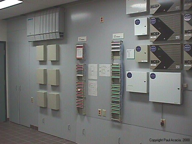
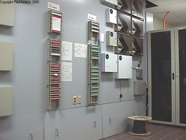
  Bell Canada phone line feeds and T1 lines entered from the plant and terminated on the first set for BIX blocks, located on the far left-hand side.  These six blocks constituted Bell's side of the demarcation point.  The plant's technical support staff did not touch these.  Tie cables led to the plant's side, where the staff could connect phones and modems quite easily.  The Phone System is rectangular box located at the upper left-hand side, immediately above the Bell BIX blocks.

  Computer network cabling from the first floor came up the access holes and traveled along the bottom of the false wall and entered the double network cabinet on the right side.  The network cabling from the second floor and the plant traveled along the top to the right side, then entered the network cabinet from below.  One meter of  extra cable length (looped inside the false wall) allowed the network cabinet to be moved about.

  Phone set cabling entered by the same sources, but traveled to the phone BIX blocks on the company's side of the demarcation point (see the green labeled BIX blocks in the photos below).  Modem lines traveled to the red BIX blocks.  

  Paging system wiring travels from the office speakers and plant area horns to one of the six Bell Canada BIX blocks on the right-hand side.  Companion System base radio cables (a wireless phone system) similarly travel to another BIX block set.

  Security system sensors and video camera cables travel along the upper portion of the false wall, and terminate on the upper right-hand side (larger gold and black rectangular boxes).

  Electrical power outlets are located at various points on the front and back side.  Isolated ground outlets are supplied for devices like the digital phone system.  A UPS is provided for the phone system as well, to allow up to a minimum of 15 minutes of service in the event of a power outage.

After:

Phone Board --- LHS    Phone Board --- RHS  

The pair of photos show the left- and right-hand side of the telecomm board.  The access panels are in place, along the bottom.  Unseen is the ventilation grid along the length of the ceiling, adjacent to the telecomm board.  The smoked-glass door of the network cabinet is seen at the far right.  Note that there is room for expansion as the plants telecommunication needs grow.


 Phone Board --- Bottom    Phone Board --- Inside  

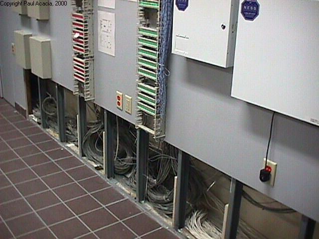
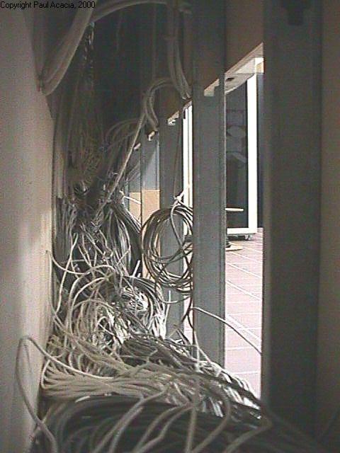
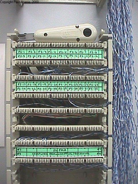
The two photos above show the access panels removed.  The steel wall studs are evident.  The second shot is taken from the "closet" on the left-hand side, looking behind the false wall.

The two photos below illustrate the simplicity of the phone and modem system.  The phone set system is colour coded in green.  To install a new phone, the technical support person simply connects a pair of wires from a phone system port (top row of phone BIX blocks) to the correctly labeled point immediately below.  This then activates the green port with the identical label, in the desired office...  Finally, the support person plugs in the new phone in that office.

                         Network Drop
The combination network drop located in each office.

Wires from the two blue sockets travel directly to the network cabinet in the Computer Room.  Wires from the green phone jack, and the red modem jack run with the network wires to the same room.  Once there they split off and terminate on the green and red BIX blocks

The set of phone BIX Phone BIX Blocksblocks, in the Computer Room.

The green phone BIX blocks
have labels that match
the green jacks in the offices. 

There is a similar system
for the red modem jacks.


Antiblast UnitAt the far end of the paging wires are speakers or horn.  This photo shows a 15 Watt paging horn, located near the ceiling in the plant.  This particular one is near the heavy stamping presses, and it is connected to a (gray) anti-blast unit.  (The presses are very loud.  When they are not running, the anti-blast unit reduces the volume of the paging horn.)


[Back to Top]

Questions or comments?   Enter your comments on our  Feedback Form

Or send mail to  [email protected]  or to  [email protected].

Copyright�2000 P. Acacia Consulting

Last modified: Monday, May 08, 2000


Hosted by www.Geocities.ws

1