Switching in Telecommunications
ATM Switch Architectures
This section describes some of the architectures for the ATM switches.
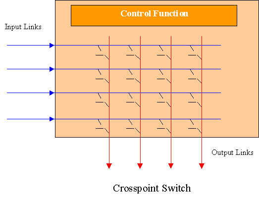
These switches employ a circuit switching technique. Their inputs and outputs are connected to a number of separate parallel data paths. The input and output paths are arranged as a matrix. A switch is located at each intersection on the matrix. Any input can be connected to any output by simply turning on the appropriate switch. Although only one input may be connected to any one output at a point in time, but a single input can potentially be connected to multiple outputs.
Crosspoint switches are simple. There is no blocking within the switch. Blocking may, however, occur at the output when two input paths request the same output. The number of required crosspoints is the square of the number of ports on the switch. The size of the switch can be reduced by connecting the inputs to the outputs through a set of intermediate data paths. However, blocking can occur in this case within the switch as there will be fewer intermediate data paths than inputs or outputs. As the switch is controlled by a centralised control function, the rate of requests to the control function increase with the size of the switch. This can cause queuing delays and contention within the control element.
External links connect to the switch via an adapter card in the bus/backplane switch. The adapter card also performs switching and routing functions. Data is transferred between the adapter cards via the common bus.
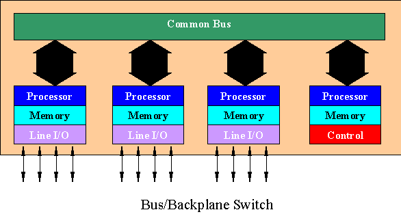
These switches are fast because of the high throughput of the parallel bus. However, this bus can only be utilised by one adapter card at a time. Thus the total system throughput is equal to the throughput of the bus. Moreover, the arbitration mechanism used to allow a specific adapter to use the bus has associated overheads. Finally, the throughput and the effectiveness of the bus fall with the increase in its size. This limits the number of adapters on the bus.
Banyan switches are a type of multistage switches. These employ a simple form of the serial stage by stage switching. A simple Banyan switch is shown below.
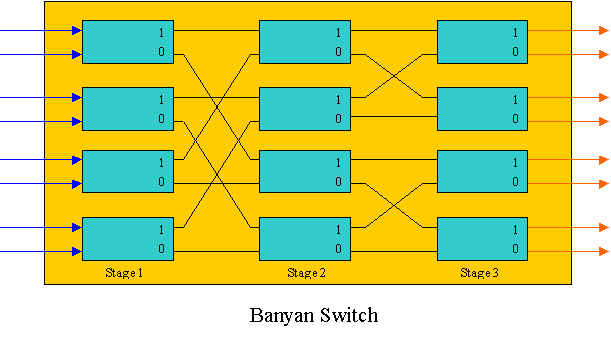
Each box in the switching matrix represents a single switching element. Each of these switching elements has two inputs and two outputs. These switching elements are connected via serial links. In practical switches, inputs and outputs are paired to form full duplex connections.
The first bit of the data stream at the input of a switching element indicates the output link on which the data is to be forwarded. The bit used to determine the routing is discarded and the remaining data block is sent to the next switching stage. In the next switching stage, the process is repeated. For instance, if the data stream 11010001 is at the input of a switching element of stage 1, the output of the switching element will be 1101000. Similarly the output of stages 2 and 3 will be 110100 and 11010 respectively. The bits discarded at each stage determine the routing of the cell through the switching element at that stage.
Banyan switches are simple, modular and expandable. These generally introduce minimal delay. One of their major disadvantages is that, if two blocks of data passing through the switch at any time need to used a common link, collision occurs. This problem can be resolved by buffering the data in each switching element. This, however, causes a delay in the switch and increases the transit delay in the network.
Previous : Functions Performed by ATM Switches
Next : Bibliography
Top : Contents
© Omar Bashir, December 1998