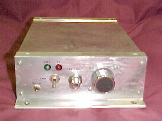
Instead of mounting the SW-40+ into a CB case as I did with the SW-20, I decided to use an extruded aluminum box I had that had originally housed the receiver unit for a remote-controlled crane. This presented a minor problem in that there was a large hole in the front panel for a multi-conductor cable connection. Another problem was that the case is much larger than the SW-40+ kit board. Both problems were solved with some PC board. I cut a small piece for the front panel. Luckily the large hole in front has four screws & nuts that held the cable connector. I drilled four holes in the PC board corresponding to the existing holes, and used the screws & nuts to fasten it to the inside of the front panel. In the middle of the large hole, I drilled a hole to pass the tuning knob pot through. The PC board was large enough to cover the smaller hole to the left, where I drilled another hole in the board and installed a pot for the AF gain control. The last hole was small enough that the nut on the shank of the on/off switch didn't pass through. Additional holes were drilled for the headphone jack and LED's.
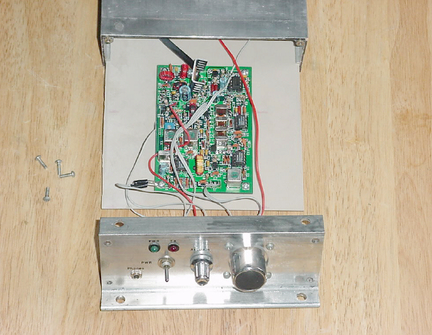
To mount the board into the case, I cut a piece of PC board the same width as the original PC board. This slides into grooves on the inside of the case that held the original board. I mounted the SW-40+ board to the larger PC board with standoffs. It slides into the case nicely.
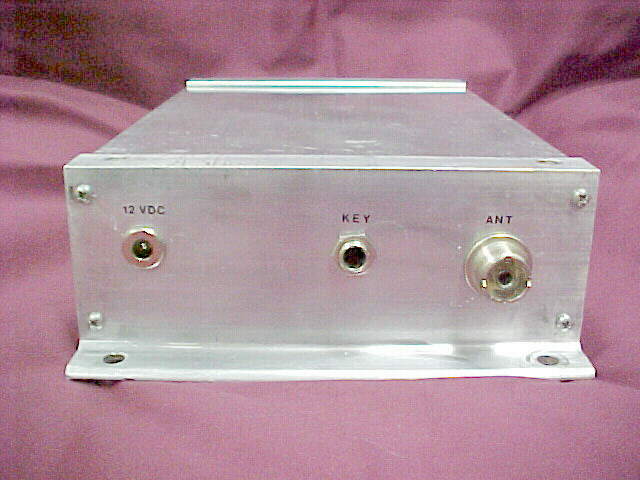
I used rub-on lettering for the front & back panels. I used clear spray paint to keep the lettering from rubbing off. This was done prior to installing the pots, LED's, switch, and jacks.
I used the SW40 for several years until I disassembled it to use the board in the MultiWonder project.