The interface requires no external power and is operated by the computer's serial port. The circuit consists of an audio transformer, a capacitor, a PC-mount 10K potentiometer, an opto-coupler IC such as a 4N25 or 4N35, a 100 Ohm resistor, a 10uF capacitor, and an LED. The optical coupler IC and audio transformers provide isolation between the HF rig and the soundcard.
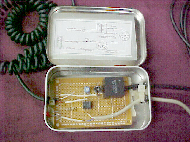
I scrounged all the parts except for the opto-isolator chip from my junk box. The audio transformer (the black box in the photo) was removed from an old computer modem. The interface was put into an Altoids box and fastened inside with double-sided foam tape. An audio cable was hardwired to the PC board, as was an old mouse cable used as a serial cable. A DB-9 connector was used on the other end of the serial cable. I used an old microphone cord and soldered an 8-pin connector on the end to connect it to the radio. I used a minature 3mm LED for a transmit light in the front side of the box. The Altoids box was painted with textured black paint prior to installing the interface inside.
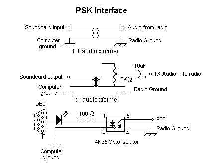
The second part of the schematic shows the TX audio from the sound card's output to the radio's mic input. A second 1:1 audio transformer is used. The TX audio level is adjusted using the 10K pot.
The third part of the schematic shows the PTT function provided by an opto isolator chip which is triggered by a + voltage on the serial port's RTS line, or pin 7 in the DB9 connector. The voltage is provided by the computer itself, which turns on the LED and opto isolator chip. The LED inside the chip turns on the transistor and keys the PTT line. Pins 3 and 6 have no connection. The second LED can be omitted if you wish, but I find it handy to have a visual indicator of when the PTT line is keyed by the computer.
You should refer to your transciever's manual to determine which pins to make the proper connections to the mic plug.