 First Generation Steering
Wheel Controls.
[ SWC Home | Second
Generation SWC | Third Generation SWC ]
[ Home | FAQ | Interfaces Available
]
First Generation Steering
Wheel Controls.
[ SWC Home | Second
Generation SWC | Third Generation SWC ]
[ Home | FAQ | Interfaces Available
]
History of the first generation steering wheel controls
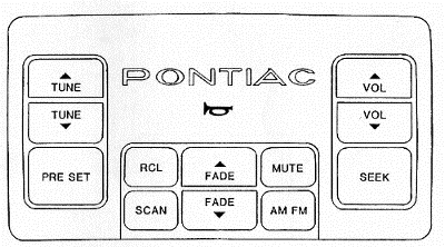
The above picture is of the first generation steering wheel control
(SWC) that GM made. I was available only on the 1986 Pontiac 6000 STE four
door sedan. It controlled a special radio made to accept the SWC commands.
The major drawback to this system is that it only controlled radio functions.
Tape deck and CD player functions were not able to be controlled by this
system. It was more of a design limitation of the radio and tape deck that
prevented the control of the decks functions. This would be resolved in
the second generation steering wheel controls.
In 1987, Pontiac included these controls in the Bonneville. Also,
a new feature was added in the radio that if the radio lost power (ie.
the radio was stolen), the radio would go into a locked up state (indicated
by "Loc" in the display) and prevent use of any functions until the MUTE
button on the SWC pad was pressed. This feature was called DELCO-LOC.
In 1988, the Firebird Trans Am and GTA were added to the models
that received these controls and a slight style change to the buttons on
the radio (they were rounded on the edges instead of the squared off like
the older models) happened.
1989 was the last year that these SWC's would be available on GM
cars. Only the 1989 Trans Am, GTA and 20th Anniversary Trans Am received
these controls. The Bonneville, 6000 STE and Grand Prix would receive the
second generation SWC's along with new radios and even the HVAC controls
which would receive commands from the SWC's.
How does this thing work?
The first generation SWC's required several new components. First
of course was the steering wheel. The steering wheel needed to be designed
to allow the SWC pad to be secured to it. Next was the SWC pad itself.
GM, as far as I know, never serviced this unit. It was a pitch item. A
very expensive pitch item. New SWC pads were about $200-$300 from the dealer.
They came in various colors (but the buttons were always gray) and included
the horn switch. Next in the chain was a new cancel cam. The standard cancel
cam had only one slip ring (for the horn). The new cancel cam had four
slip rings and six infared LED transmitters. This is also an expensive
replacement piece. The four slip rings handled the horn, ignition power,
ground and illumination power. The cancel cam had a standard horn connector
and a plug with four pins in it (for the SWC pad). The infared (IR) light
emitting diode (LED) transmitters turned on and off with the digital signal
sent from the SWC pad when you pushed a button. There are two IR receivers
on the turn signal switch. The IR LED transmitters (six of them) are placed
on the cancel cam in a circular arrangement, evenly spaced. This arrangement
allowed at least one of the transmitters to be in the line of sight with
one on the receivers no matter where the steering wheel was. This formed
an optical slip ring which was necessary because using a standard slip
ring would cause too much digital noise and interfere with the correct
decoding of the transmitted signal. This optical slip ring solved that
problem. As I mentioned above, the turn signal switch had to be modified
to accept the four slip rings on the cancel cam as well as the two IR receivers.
Lastly, the car harness had to be made to accept the new turn signal switch
and supply it with the correct power, ground and illumination signals and
well as take the signal from the IR receivers and supply it to the radio.
Below are some block diagrams to help you understand the entire system.
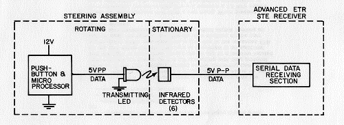 This diagram shows a simplified block diagram of the entire system.
The infrared detectors in the turn signal switch number only two, not six
as shown. There are also six transmitting LEDs in the cancel cam.
This diagram shows a simplified block diagram of the entire system.
The infrared detectors in the turn signal switch number only two, not six
as shown. There are also six transmitting LEDs in the cancel cam.
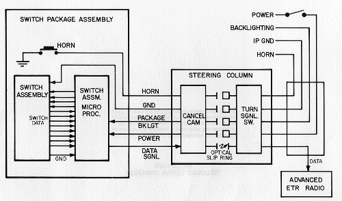 In this diagram, a more detailed breakdown of the system is shown.
The switch package assembly is what I refer to as the SWC pad. The steering
column contains the cancel can and the turn signal switch. And you can
see the data path to the radio.
In this diagram, a more detailed breakdown of the system is shown.
The switch package assembly is what I refer to as the SWC pad. The steering
column contains the cancel can and the turn signal switch. And you can
see the data path to the radio.
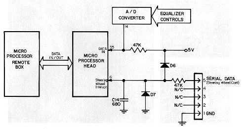 Here, we see how the internal radio circurity is configured. On
the back of a first generation SWC capable Delco radio, there is a five-pin
connector on the back (in addition to the normal connectors). Only two
pins are used as you can see. D6 and D7 are used as spike suppression devices.
The asynchronous serial data is fed through a 47K resistor to pin six of
the microprocessor. The program in the microprocessor decodes the serial
data and performs the desired function pressed on the SWC pad. Note here
that the tape deck is not connected in any way here. This is why the first
generation SWC's cannot control deck functions. The decks used in these
units had no data communication to the microprocessor head. Second generation
compact disc decks did have communication to the microprocessor head and
therefore could control deck functions. Some tape decks I believe received
communication capability and could also be controlled by the SWC's.
Here, we see how the internal radio circurity is configured. On
the back of a first generation SWC capable Delco radio, there is a five-pin
connector on the back (in addition to the normal connectors). Only two
pins are used as you can see. D6 and D7 are used as spike suppression devices.
The asynchronous serial data is fed through a 47K resistor to pin six of
the microprocessor. The program in the microprocessor decodes the serial
data and performs the desired function pressed on the SWC pad. Note here
that the tape deck is not connected in any way here. This is why the first
generation SWC's cannot control deck functions. The decks used in these
units had no data communication to the microprocessor head. Second generation
compact disc decks did have communication to the microprocessor head and
therefore could control deck functions. Some tape decks I believe received
communication capability and could also be controlled by the SWC's.
Can an interface be made to work with these controls?
The answer is YES! I have decoded the serial data and currently
am designing an interface so these controls can be used with aftermarket
radios. If you are interested in an interface for this type of steering
wheel control (first generation), let me know! Since this is an older system,
I haven't been really working on it hard. Seems the third generation SWC's
has a wider market (it came on more cars) and is easier to interface with.
The second generation is the most difficult to interface with as it uses
a bi-directional serial data bus and requires much more decoding as several
components share this data bus.
Send mail to the Webmaster [email protected]
with questions or
comments about this web site.
Copyright © 1998 by Carl Miles
Last modified: June 30, 1998
This page has been visited  times since 7/6/98! Thanks!
This page hosted by  Get your own Free Homepage