QUAD EIGHT
CA-127 TO CA-227 CONVERSION
&
Please email me if you have any suggestions or warnings,
or perhaps even some other Quad Eight information. Thanks!
Jesus Cruz - email: more_quad_eight-AT-yahoo.com
UPDATES
30 Jan 2004 - Added PDF circuit board trace image.
31 Jan 2004 - Changed large images to Acrobat PDF files.
12 Feb 2004 - Added DIY CA227 page
DISCLAIMER:
This is my card. I don't guarantee that the
same changes will work for you, but I hope they would. Please
check all of my work before setting off and soldering. GOOD LUCK!
HOW IT BEGAN
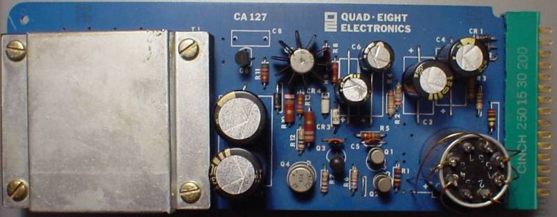
A friend of mine had acquired some Quad Eight
line cards, like the one you see above, and had been told (and
had heard) that they can sound really nice. Equipped with some
schematics and pinout diagrams, he gave them to me and said "Rack
'em".
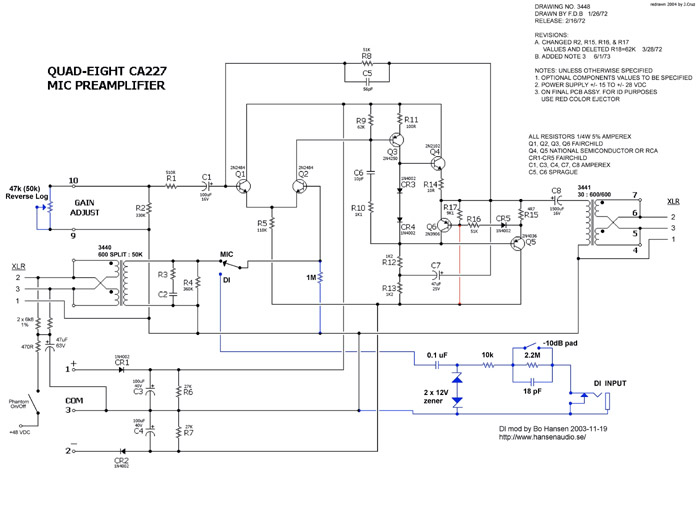
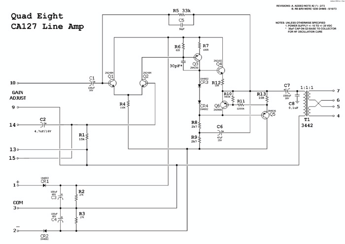
I worked off of the following shematics (click
on the schematic to download a larger .pdf file) :
 NOTES:
- Apparently there are different versions of
Quad Eight's CA-127. The one on this page seems to be the first
one.
- When I modified the CA-127 cards, I kept
the output transformers, which aren't exactly the same as those
on the CA227. The CA-127 schematic I have shows that circuit
using an output transformer with a ratio of 1:1/1 (secondaries
can be wired in series or parallel). My friend had been recommended
to wire the output secondaries in parallel, by the person he
bought them from. Thinking about it now, this would seem to act
as a step down transformer (opposite of the CA-227), so if anyone
has anything to add here, please contact me.
- The "blue" in the schematic denotes the D.I. circuit mod
that Bo Hansen, of Sweden, was so kind to help out with. You
can check his stuff out at http://www.hansenaudio.se/.
He also dontated the +48 scheme and XLR notation. Tack, Bo!
- The "red" in the schematic denotes a section in which
I am unclear. The original schematic that I have shows the part
in red, but a friend of mine, who has been letting me know how
his mod is working says he has some original CA-227 cards without
that connection. If you choose to wire it as the schematic, it's
as easy as a jumper.
- The "Gain Adjust" between pin 9
&10 was noted on a CA-127 application note I have, as resistors
of different values, giving varying gains. You can find that
paper here: CA127_APP_NOTES.pdf
- I used a UTC "Ouncer" O-10 transformer
(wired backwards) for the input. That gave me the option to choose
between 3 impedances. It seems logical that you could use any
transformer with the right ratio.
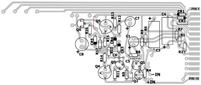
CA227 PARTS OVERLAY AND PCB
Note: the PCB for the CA127 and CA227 have the same traces
 NOTES:
- I used pins 11-14 & 8 for connecting
the input transformer secondaries.
- Part numbers on the overlay refer to the
part numbers on the CA-227 schematic.
- The red jumper near Q5 refers to the red in the schematic.
- C1, C7, & C8 are originally axial capacitors,
and the original pcb will not show the traces as such, but further
apart. I had redrawn the pcb traces to allow me to use radial
caps instead.
- In my application of the D.I. mod, I wired
R4 directly across the secondaries of the input transformer and
wired the 1M resistor for the modded circuit in place of R4,
so pin 15 became the wire coming from the D.I. section.
- "+IN" & "-IN" refer
to the secondaries of the input transformer.
- Here is the PCB
drawing. It is real life size, based
on the CA-127 card I have, with the original spacing for the
axial capacitors. Resolution is 600dpi. I have made my own CA-227
derivative from the layout and it is working quite nicely.
...more to come...