 |
|
|
|
|
|
|
|
|
|
|
|
|
|
|
|
|
|
|
|
|
|
|
|
|
|
|
|
|
|
|
|
|
|
|
|
|
|
|
|
|
|
|
|
|
|
|
|
|
|
|
|
|
|
|
|
|
|
|
|
|
|
 |
|
|
|
 |
|
|
|
 |
|
|
|
BUILDING A NEWTONIAN TELESCOPE |
|
|
HOME |
|
|
|
|
|
|
|
|
|
TELESCOPES |
|
|
|
|
|
(1) INTRODUCTION |
|
|
|
|
|
|
|
|
(2) BUILDING THE TUBE |
|
|
|
|
|
(3) MIRROR CELL ASSEMBLY |
|
|
|
|
|
(4)MARKING THE MIRROR |
|
|
|
|
|
(5) FIXING THE MIRROR |
|
|
|
|
|
(6) DIAGONAL MIRROR AND SPIDER |
|
|
|
|
|
(7)ASSEMBLY |
|
|
|
|
|
(8) DOBSONIAN MOUNT |
|
|
|
|
|
1 - INTRODUCTION |
|
|
|
Making your own Newtonian telescope is a most enjoyable project both for the hours of enjoyment you're going to have using it and the pleasure of making a scientific instrument of some considerable size. Where to start ? - the major decision, obviously, is what size of mirror to buy. The larger the better ? well, yes, but larger mirrors mean longer focal lengths, hence longer tubes. Too big and it will soon become a chore to get it out the garage, set it up, let it cool before use. Someone said the best telescope is the one you use most. |
|
|
|
There is plenty of free advice on the Internet but the consensus seems to be that a 6 inch (150mm) to 8 inch; (200mm) diameter is about the optimum for suburban use. Such a size is also capable of fitting inside a car for more adventurous types. The typical focal ratio is f8 for all-round performance giving focal lengths of 48 inch and 64 inch respectively. These dimensions automatically define the length of the tube as we shall see later. |
|
|
|
There is a most useful program - 'Newt' available as freeware available as a download from Dale Keller called newt25.zip which expands to newtwin.exe. By feeding in your mirror diameter and a few other parameters, the program calculates tube diameter, length and a host of other essential dimensions. |
|
|
 |
|
|
|
Here's a screen-dump from 'Newt' for my t'scope. As you refine the design, all the dimensions are calculated for you and available for viewing and printing. |
|
|
|
The arguments for and against baffles can be followed on the Internet; I chose to fit baffles mainly because they would act as formers for construction. I can see that if a traditional circular tube design was chosen (plastic pipe or cardboard tube), baffle fitting would be quite exciting. I chose to make an octagonal tube from thin plywood, mainly for lightness but also because I like woodworking. |
|
|
|
Let's look at the overall plan. This is just a thumbnail pic - click to load a larger, more readable version. |
|
|
|
 |
|
|
|
CONSTRUCTION OF THE TUBE |
|
|
|
In essence, the construction consists of eight identical boards of 1/8 inch ply glued around nine 1/8 inch octagonal formers (baffles), each with a 7 1/4 inch diam cut-out - very much like the traditional building of a model aeroplane or boat. The front view in the plan above shows the major dimensions. I cut the baffles first as 8 1/4 inch squares and then cut the central hole in groups of three using a router and home-brew circle cutting jig. If you don't have a router - get one, they are immensely useful tools for all sorts of jobs. All the baffles and the 1/2 inch ply back plate were then pinned together and cut and sanded to the finished shape. This ensures they are all identical in size. |
|
|
|
The eight inch nominal 3 1/2 inch x 48 inch boards were then cut with 22 1/2 deg. bevels (approx !)on the side edges and marked with the positions of the baffles. At this stage I had to alter the position of two of them to allow them to clear the focusser holding bolts (I don't think I altered the dimensions on the drawing!). One of the boards was lightly pinned to the flat work-bench and the baffles glued to their marked positions using woodworking hot-melt glue. They should all be mounted square and vertical. One board was then carefully glued on ensuring that no twist was being built into the construction. The opposite board was next, and then alternate boards until one remained. TIME TO STOP ! The last board would not be put on until the inside was painted. A quick dob round with some P.V.A. glue to strengthen the joints and the assembly was left to set overnight. |
|
|
|
 |
|
|
|
There were now a few details to attend to. Thinking ahead for once, I glued small pieces of ply inside the tube to reinforce stress points - i.e. under the focusser, under the handle and halfway down the tube inside the bottom where I then glued two pieces of dowel 3 inch apart to act as locating aids in the Dobsonian cradle. Having marked the position of the mirror cell inside the tube, four holes were drilled at the appropriate points to screw into the 1/2 inchply cell back plate. This was then removed for mirror fixing. |
|
|
|
 |
|
|
|
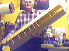
At this stage it looked like this |
|
|
|
The inside was given a first coat of matt-black blackboard paint and the inner side of the last board was painted. Doing it this way ensured at all parts of the interior received at least one coat of paint, as later, it would be difficult to reach every nook and cranny. The final board was then glued on - the tube was essentially complete . |
|
|
|
Now for the hard bit - I decided the interior was not as black as it could be - so, another coat of paint, applied with a cut-down brush, was brushed over as much as possible. Then, whilst the paint was still wet, I threw a copious amount of sawdust inside attempting to cover all areas. The whole thing was then left to dry and the loose sawdust shaken and vacuumed out. The whole thing was then given another coat of paint to seal in the sawdust. When dry the finish was very rough and very dark - I don't know what more can be done in this direction. The baffles certainly help. I've since stuck black flocked plastic on some of the panels (those I could reach). The mirror end of the tube looked a bit flimsy, so I wrapped a 1 inch wide band of fibre-glass tape and resin round the outside to strengthen it. Finally, the surface was given a coat of sanding sealer, rubbed down and then painted with two coats of hammer - finish gloss white - Luverley !. |
|
|
|
 |
|
|
|
Here's the front end with the focusser, a home-brew red-dot finder and a home-brew 6 x 30 finder-scope The handle was added to stop me hauling the 'scope around by the spider ! |
|
|
|
|
|
|
|
 |
|
|
 |
|
|
|
|
|
|
|