 |
|
|
|
|
|
|
|
|
|
|
|
|
|
|
|
|
|
|
|
|
|
|
|
|
|
|
|
|
|
|
|
|
|
|
|
|
|
|
|
|
|
|
|
|
|
|
|
|
|
|
|
|
|
|
|
|
|
|
|
|
|
|
|
|
|
|
|
|
|
|
|
|
|
 |
|
|
|
HOME |
|
LONG EXPOSURE MOD |
|
|
|
|
|
I've recently been experimenting with a slightly different approach to CCD imaging.The camera now being worked on is an SK-1004 XAC B/W miniature TV camera board. I obtained this from RF Conceptshere in the UK. The output from the board is suitable for feeding directly into a TV monitor or VCR and hence provides real-time imaging. There is no output suitable for feeding directly into a computer (but see below). |
|
|
|
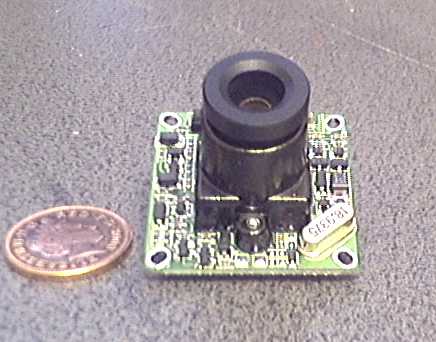
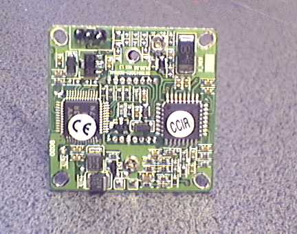
Here are shots of the bare board as delivered - well, not quite - it arrived with a tiny audio daughter board on the back. I removed that (not needed) and re-made the 3 connections to the main board - video out, 12v in and earth. Note that the output is in CCIR (PAL) format only. The board is 32mm (1.25") square and is fitted with a 3.6mm f2.0 lens. This unscrews, which is as well because it won't be needed for the modifications. It has however, a standard thread and will interchange, for example, with the lens in the Philips Vesta series of cameras. |
|
|
|
 |
|
|
|
 |
|
|
|
So, what's the point of all this ?. Well, here are a few details from the specification - note particularly the sensitivity of the CCD - 0.003 lux ! that means I can see stars on the TV monitor, suggesting all sorts of possibilities. See also this .pdf file.from Sony. |
|
|
|
1/3 inch Sony EXview HAD CCD (TM) type ICX255AL |
|
|
|
500 x 582 pixels |
|
|
|
pixel size - 9.8 um H x 6.3um V |
|
|
|
Max sensitivity - 0.003 lux |
|
|
|
Furthermore, John Grove of the QCUIAG mail group has published a modification on his web-site to the camera enabling it to take long exposures. Coupled with its high sensitivity, the images obtained are stunning. Details of how I carried out the modification are here - |
|
|
|
LONG EXPOSURES FOR THE 1004 |
|
|
|
My first step was to built a box to house the board as described here. I've put a couple of diagrams showing the major construction details and dimensions on this page. |
|
|
|
 |
|
|
|
 |
|
|
|
|
|
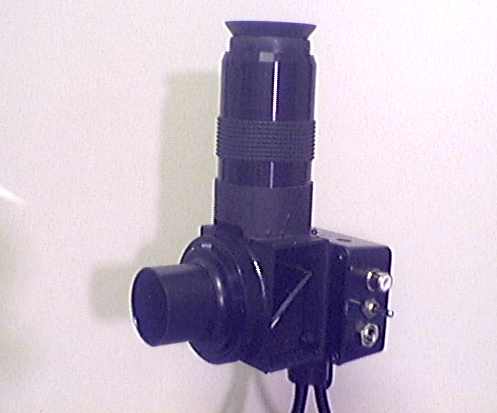
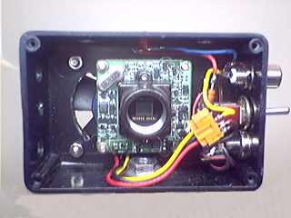
The 2 pictures here show the finished result - the small project box on the back houses the 1004 board, power input and video out sockets, an on/off switch and a 1 1/2 " square cooling fan, most important as the circuit gets quite hot in use. I've also incorporated a 22ohm dropper resistor in the power input to lower the voltage to the board to approx 9.5 volts - still works fine but runs cooler. The camera board is held in the box by 4 x 8BA bolts with spacers to get the CCD close to the front of the box - this is important to minimise the amount of in-travel needed on the telescope focuser. The board is spaced 13mm back from the front. |
|
|
|
 |
|
|
|
 |
|
|
|
|
|
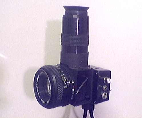
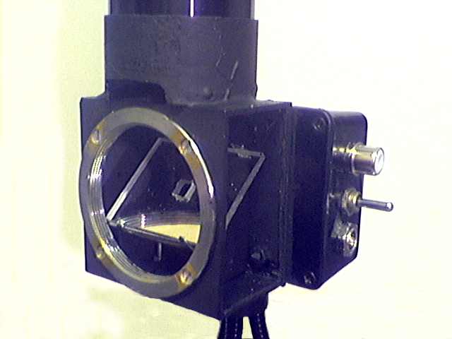
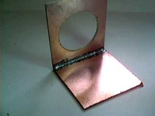
The front box was soldered up from printed circuit board stock.The box houses a 45 degree mirror for viewing the target through a 40mm eyepiece on top. I had to unscrew the 1.25" diam collar off the eyepiece in order to get it close enough to the mirror to focus. A bit of experimenting is needed here to find a suitable one. |
|
|
|
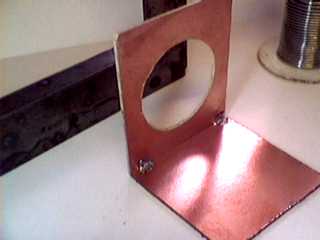
How to make a box from blank printed circuit board may not obvious to all, so here's how : |
|
|
|
 |
|
|
|
Cut all the pieces and finish the edges to ensure they are all square.Drill and cut all holes at this stage. |
|
|
|
|
|
 |
|
|
|
Tack solder the pieces together just enough to hold. Note the square - this is used whilst soldering to make sure the pieces are kept square during the process. This is important because the solder will pull the boards inwards off-square as it cools and shrinks. |
|
|
|
|
|
 |
|
|
|
Run a filet of solder right the way along the edge to complete the joint.A hot soldering iron is needed for this. Repeat the process for all parts of the box. |
|
|
|
|
|
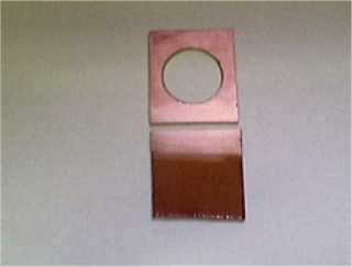
The mirror doesn't flip - its got a small square hole in it which is aligned with the CCD. This was easily cut because the mirror is made from plastic !. It's best to start by cutting a much smaller hole and enlarging it in stages. Because I've mounted an old 42mm camera thread on the front, the camera can be used on the telescope by means of a standard T- adaptor or used with conventional 35mm camera lenses for (slightly) more wider angle shots. The interior view above shows how the board is mounted, the fan behind and plenty of room for additional circuitry for the long exposure mod later. Note - I've glued a 1/4" Whit nut in the base as a tripod mount.See this page for dimensions etc. |
|
|
|
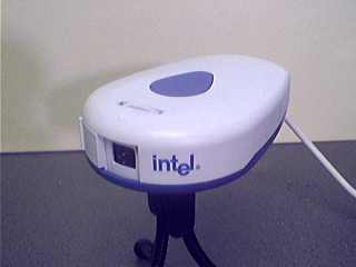
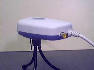
As mentioned above, the output from the board is the standard 1 volt 75ohm video out so some means is needed to get that into the computer for image processing. The conventional way is to fit a video-grabber board into the computer -Initially I chose a slightly different route - another CCD web-cam in my collection is the Intel Pro CS430; this has a very handy video - in socket on the back and comes with the software to convert the video to .AVI or .BMP files via the USB lead to the computer - very neat !. So, for the very reasonable price of a web-cam we get a converter/ frame grabber as well - problem solved. This is not fast enough for the modified long-exposure camera - a Hauppauge WinTV Go card is used. |
|
|
|
 |
|
|
|
 |
|
|
|
|
|
Here's the front and rear views of the Intel camera showing the yellow video - in socket. |
|
|
|
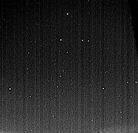
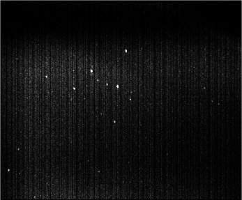
Results - Around mid-summer here in the UK the night sky never gets really dark; even after 1am there is still a glow above the horizon so serious testing of the camera will have to wait a few months. I managed a crude test of the unmodified camera with a 6.3 mm 50 deg FOV lens by pointing it out the window at Pegasus for 2 mins. The resultant 240 video frames were captured via the Intel cam as an .AVI file and subsequently stacked using 'Astrovideo' and the .FIT file level adjusted in 'Gimp'. No dark frame subtraction was done so the CCD noise is apparent as also is the light sky. Stars below mag 6.4 can be seen on the original. Also, here's an image of Cassiopeia. |
|
|
|
 |
|
|
|
 |
|
|
|
|
|
Roll on Winter ! (only joking) |
|
|
|
 |
|
|
 |
|
|