| WARNING! THESE ARE THE STEPS I DID TO INSTALL MY MSD IGNITION SYSTEM. THE FOLLOWING PICTURES AND TEXT ARE JUST GUIDELINES. THESE ARE NOT APPROVED MSD INSTALLATION INSTRUCTIONS. THEREFORE I ASSUME NO RESPONSIBILTY FOR DAMAGE DONE TO ANY EQUIPMENT OR ANY PART OF YOUR AUTOMOBILE DUE TO INSTALLATION BY FOLLOWING THESE GUIDELINES! |
| Materials needed Flat head screw driver Liquid Electrical tape Heat shrink tubing with adhesive Drill bit Drill Socket wrenches Wire crimpers Wire splices Electrical tape Rags Pliers Dremal cut off wheel or hacksaw heatgun LOTS OF TIME! |
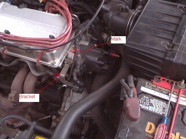
| Disconnect battery. Place a mark on the head and the distributer so you can align them up properly and not have your timing off when you reinstall the distributer. Look at piture # 1 below. Disconnect the spark plug wires from the distributer. Disconnect the connector thats connected to the distributer. Remove the distributer cap and remove the rotor. There are 2 bolts that need to be removed in order to take out the distributer. There is also a bolt that holds a bracket on the distributer. Remove the bolts. Place a rag underneath the distributer. With a slight twisting motion pull the distributer out. |
 |
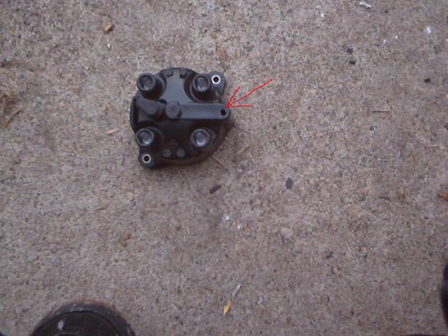
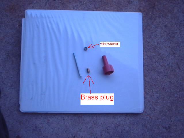
| We are going to modify the distrubuter cap first. The next 7 pictures will show you how. In picture # 2 below you will see 4 pieces that are going to be needed if your using the external coil. Take the screw that you see in the picture # 2 and match it to a drill bit thats just slighty smaller then the screw. Sorry i dont know the exact size of the drill bit. Drill a hole in the cap as shown in picture # 3. |
 |
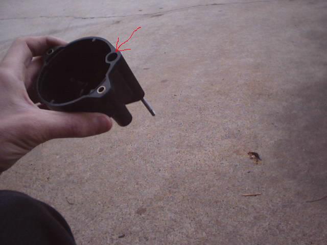 |
| If you drilled it just right you will notice a spring and a piece of aluminum come out of a hole on the underside of the cap. Where the arrow is pointing. If the piece didnt come out then you need to pull it out with someting. |
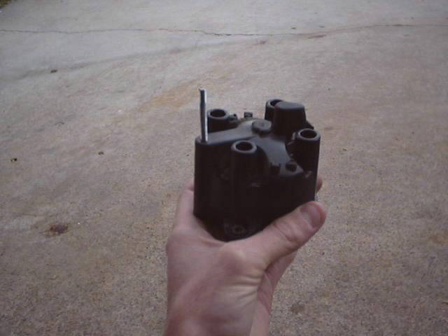
| Now take the screw and the wire washer as shown in picture # 2 above. Slide the wire washer on the screw and screw the screw and wire washer in the distributer cap as shown in picture # 4. Dont over tighten the screw you will strip out the cap. It should look like picture # 5 below when finished. |
 |
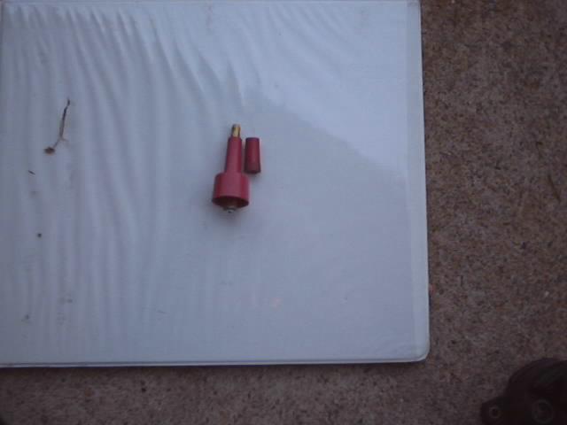 |
| Now we need to modify the tower to look like the piece to the right in picture # 6. |
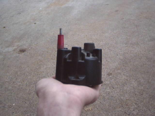 |
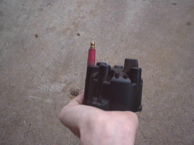
| Once the tower has been modified screw it on to the screw. It will look like picture # 7 below. Then take the brass plug (shown in picture # 2 above) and screw that on top of the tower. Use a screw driver to keep the screw from turning while you tighten the brass plug with some pliers. Now you will notice that the screw is to long so you need to cut and grind down the screw to the top of the brass plug as show in the picture # 8. |
 |
| PIC # 1 |
| PIC # 2 |
| PIC # 3 |
| PIC # 4 |
| PIC # 5 |
| PIC # 6 |
| PIC # 7 |
 |
| PIC # 8 |
| You are now finished modifying the distributer cap. |
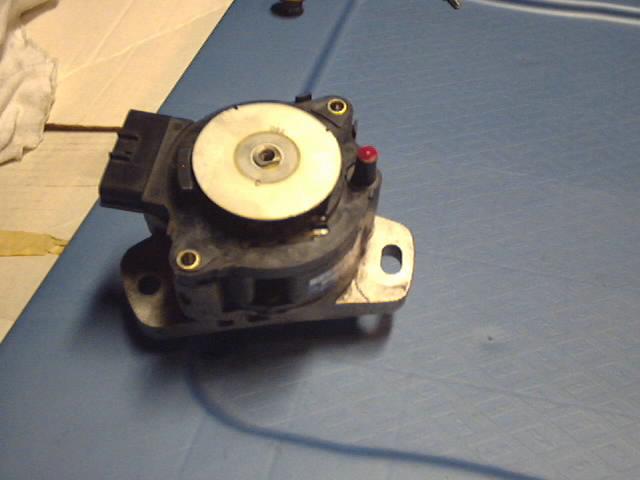
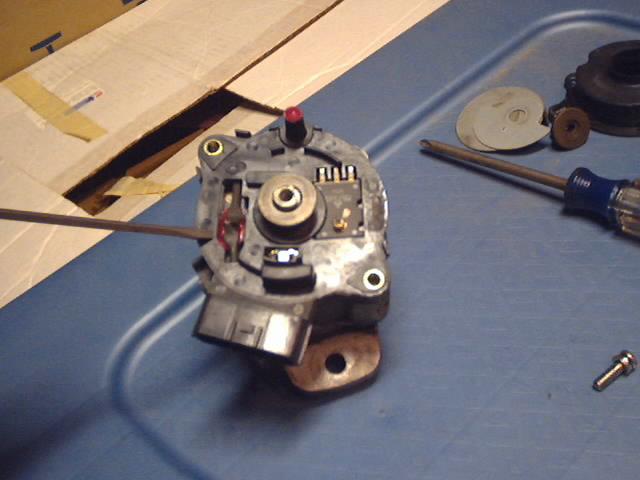
| Now its time to modify the actual distributer. The mod is simple but please follow the directions very carefully. In picture # 9 you will notice that the tower looks like it was drawn in. I had to do that because later in distributer modification you will need to cut off the tower. Picture # 9 is what your distributer looks like at the moment. |
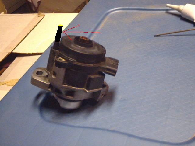 |
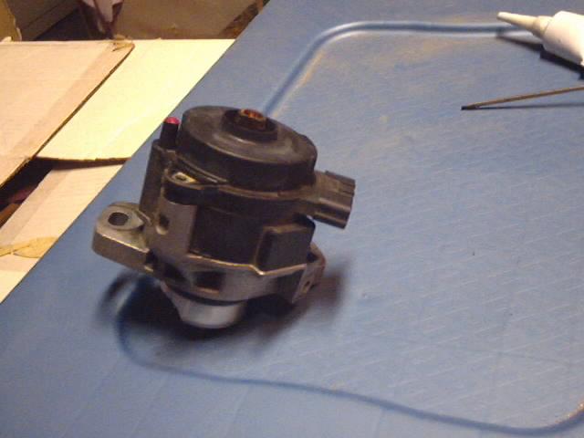
| In the next few steps here is where you will need the liquid electrical tape. ?Grab your cutting device of choice and cut off the tower on the distributer. Do not cut the tower all the way down to the base of the distributer. Leave about 1/2 to about 1/4 of an inch of tower from the base of the distributer. Look at picture # 10 for visual. Once you have cut off the tower put a dollup of liquid electrical tape on top of the exposed tower. Look at picture # 10. Let the liquid tape dry then apply another dollup of liquid tape. Let the liquid tape dry. You dont want any of the cut tower exposed. |
 |
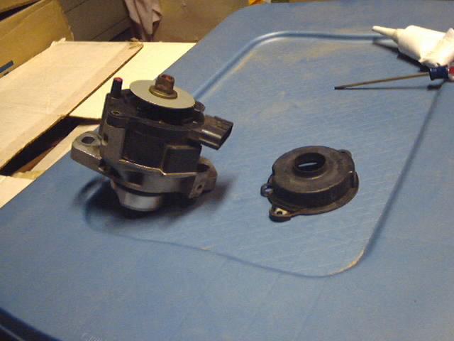
| Now that the liquid tape is dry your gonna remove the dust shield as shown in picture # 11. The dust shield should lift off the distributer quite easily. |
 |
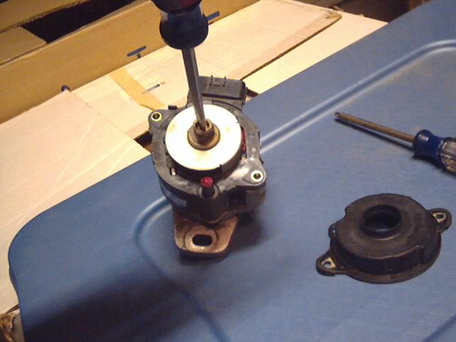
| In picture # 12 the center screw needs to be taken out. But its not possible because the center unit will spin. So in picture # 13 this is how your gonna lock the center unit. Once you have broken the screw loose you can remove the locking screw driver from the bottom of the distributer and you can keep the unit from spinning with your fingers. |
 |
 |
| PIC # 9 |
| PIC # 10 |
| PIC # 11 |
| PIC # 12 |
| PIC # 13 |
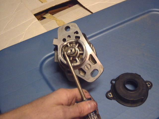
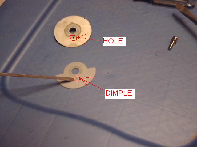
| PROCEED SLOWLY AND NOTICE THE WAY THESE NEXT 4 PIECES COME OFF! Sit the distributer on its end so the screw is facing up. Take out the screw and set aside. Take off the triangle looking nut and set aside. If you notice, the triangle looking nut is keyed on the bottom. Now look at the round disk that the triangle looking nut was sitting on. Picture # 14 That round disk has 2 key ways. There is a key where the disk sits on the center shaft and theres a small hole on the face of the round disk. There is another disk that sits under the disk you are looking at right now in Picture # 14. Lift off the top round disk and you will see the bottom disk shown in Picture # 15. Its only half round. Take a good look at the bottom disk. You'll notice there is a dimple on the face of the disk. The dimple sits in the hole of the disk that sits on top. |
 |
 |
| PIC # 15 |
| PIC # 14 |
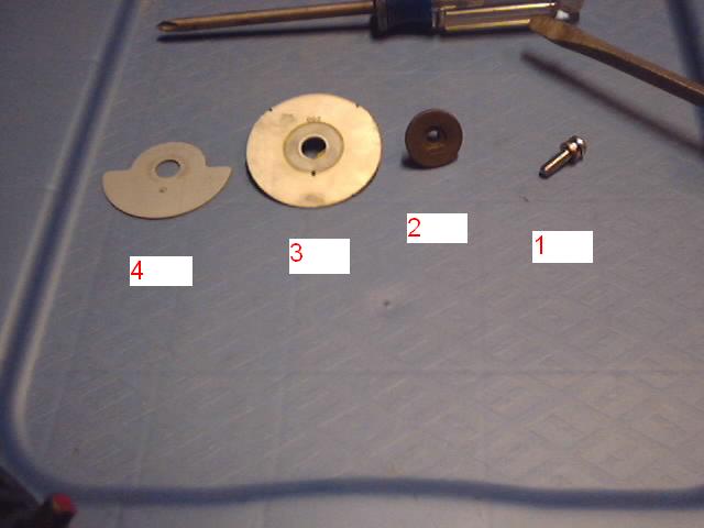
| Picture # 16 shows all the parts that you just took off. They are numbered 1 thru 4. Part number 1 being the first piece you took off and number 4 being the last piece you took off. |
 |
| PIC # 16 |
| Now that the insides have been taken out now we need to modify the internal coil of the distributer. We will be looking at Picture # 17 through out the process. You will notice that Picture # 17 is a picture of a modified coil. I will expalin in detail what needs to be done and what to look for. Notice where the screw driver is pointing at on the coil. You will see 2 small silver or gold colored screws and 2 silver or gold colored eyelet connectors being held down by the 2 small screws. Take those 2 screws out. We will not be using the 2 small screws again. The eyelet connectors are what supplies the internal coil voltage. We need to eliminate any possible chance of any voltage getting to the internal coil. The first thing to do is to cover the eyelets with heat shrink tubing. (I prefer the heat shrink with adhesive) Make sure you cut off enough shrink tubing to completly cover the eyelets. Once the heat shrink has been installed and shrunk the next step is to cover the contacs underneath the eyelets where the 2 small screws screwed into. Break out the liquid tape and carefully lift the eyelets and cover the contacs with a thin coat of liquid tape. You need to keep the heat shrink covered eyelets from resting on the fresh liquid tape. So you can either carefully and slighty bend up the eyelets or some how hold them out of the liquid tape until it dries. Once the liquid tape dries apply another coat of liquid tape if you can see any hint of the screw holes that the 2 small screws were screwed into. Once the liquid tape dries you can now begin to reassemble the distributer cap. CAUTION MAKE SURE THE EYELETS AND OR THE HEAT SHRINK IS NOT STICKING ABOVE THE CAVITY THAT THE EYELETS ARE SITTING IN. IF THEY ARE THEN THE ROUND DISK WILL HIT THE EYELETS WHEN IT IS ROTATING! |
 |
| PIC # 17 |
| The reassembly process is reverse of the disassembly process. Refer to Picture # 16 for reassembly. Take part number 4 and put that on the center shaft of the distributer. Make sure that the dimple shown in Picture # 15 is facing up (away from the coil). Take part number 3 and place that on top of part number 4. Remember that part number 3 has a hole on the face of it where the dimple of part number 4 goes into. Also remember that part number 3 is keyed to the center shaft of the coil. Next place part number 2, the triangle looking nut on top of part number 3. Remember that part number 2 is also keyed to the center shaft. Lastly, take part number 1, the screw and screw it in to the center shaft. Now tighten the center screw by locking the center shaft like you did in Picture # 13. Now rotate the center shaft from the bottom of distributer with your finger and make sure that there is no interference from the heat shrinked eyelets and the overhang of the top round disk. In other words make sure the assmebly moves nice and smooth in a complete rotation. Reinstall the dust shield on the distributer that you took off in Pictures # 10 and 11. You should now have a distributer that looks like Picture # 18. Reinstall the rotor. It only goes on one way. CONGRATULATIONS YOU JUST MODIFIED YOUR DISTRIBUTER! ALMOST DONE! |
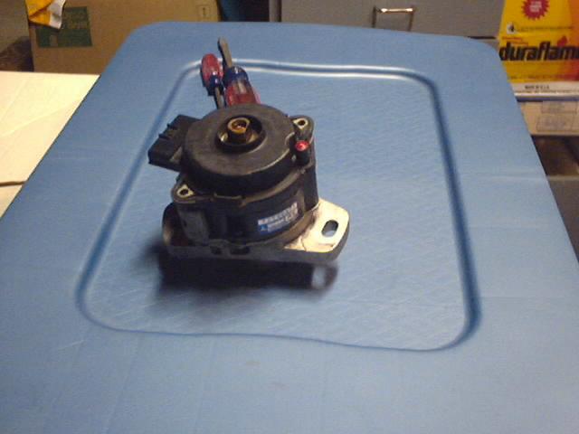 |
| PIC # 18 |
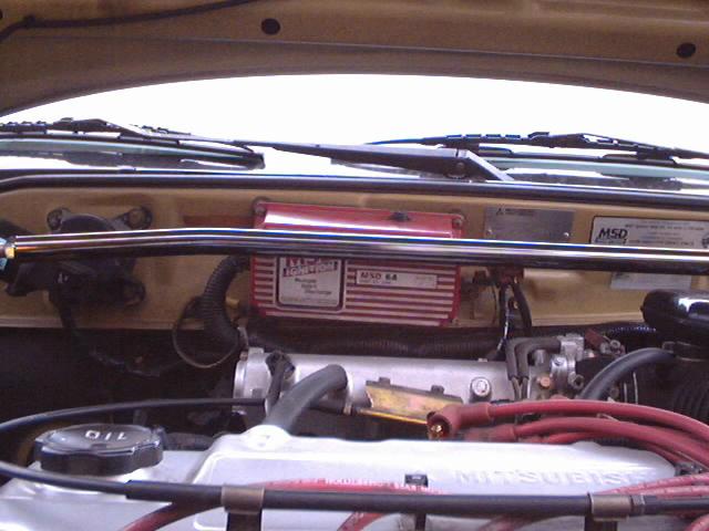
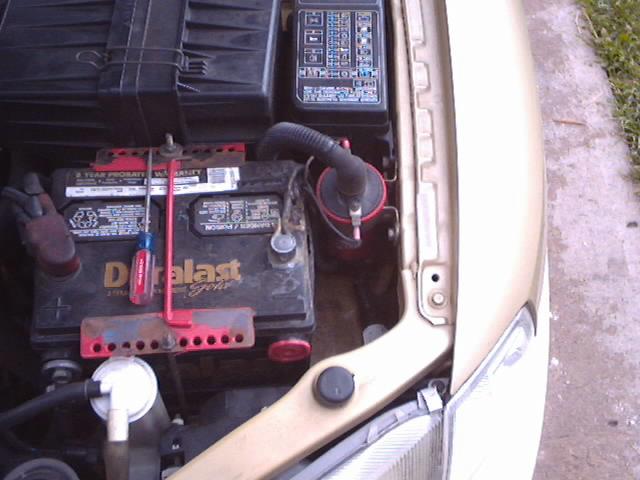
| Picture # 19 shows the ideal location i found to mount the msd box. |
 |
 |
 |
| In Picture # 20 this is where i mounted my external coil. But the location is up to you. |
| Once your msd box and external coil are mounted do a rough layout of the wires. The small black and orange wires will goto the external coil. These wires provide the power for the external coil. There is a white wire coming out of the msd box that needs to be routed to your distributer. This is the trigger wire. The small red wire gets hooked up to a switched 12 volts wire. This is the on off switch for the msd box. The heavy red wire goes to the Positive side of the battery and the heavy black wire goes to a good ground point. THE GREEN AND VIOLET WIRES WITH THE CONNECTOR ARE NOT USED! |
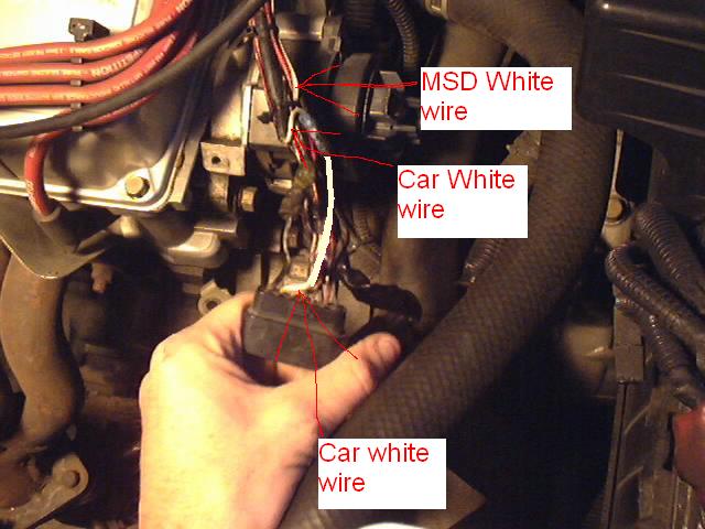
| The wires that are being focused on in this install is the WHITE wire that is coming out of the msd box and the white wire that is going to the connector that connects to the distributer. Remove any tape from the harness so you have access to the wires going into the distributer connector. Look at Picture # 21 to see an example of what needs to be done. The white wire from the msd box needs to be spliced in to the white wire thats going in to the connector. Cut the White wire in half about 2 inches from the connector. Strip the white wire that is connected to the connector and crimp a wire splice on it. Now strip the end of the white wire coming from the cars harness and strip the end of the white wire coming from the msd box. Twist those 2 white wires together and crimp them in the wire splice that is crimped on the white wire that is going into the connector. Soldering the msd white wire will be the easiest method. Just make sure you solder the wire 2 inches away from the connector. |
| PIC # 19 |
| PIC # 20 |
| PIC # 21 |
| CONGRATULATIONS YOU ARE DONE MODIFYING YOUR 1.5L MIRAGE DISTRIBUTER. |
| Reinstall the distributer. The distributer assembly is keyed and will only go in one way. Turn the rotor to line up the key to your cam shaft and lighty push the distributer assembly with a twisting motion back in to place. Line up the marks you made in the very first step and install and tighten the distributer hold down bolts. Re-attach the bracket you took off in Picture # 1. Reinstall the distributer cap. Reconnect the connector to the distributer. Run a coil wire from the external coil to the new distributer tower. Clean up, recheck all bolts, screws, connectors, spark plug wires, etc etc. Reconnect power and start it up! |
| 1.5L Mitsubishi Mirage MSD Ignition with external coil install. By Angel D E T COUPER |