If you're going to build a stationary steam engine, more than likely you'll need to build a crankshaft. If the crankshaft has a shaft on both sides of the center crankpin, you'll need to turn the crankpin to an accurate diameter with an accurate offset from the main shaft.
Here's a technique my father showed me, which I've found to be quite effective. It uses a fixture in order to turn the crankpin between centers.
BTW - The crankshaft in the photos is for a PM Research #5 "Coke Bottle" engine.
First, use a center finding device to mark the center of the rough crankshaft. If the diameter of the casting is close to final dimensions, be careful here to make sure the center is accurately located. Center punch the mark.
Mount the crankshaft vertically in your drill press, pick up the center, and use a center drill. Switch ends and
repeat.
The next step is to machine the main shaft to dimension. This has to be done one side at a time, since the lathe dog will interfere with the side closest to the headstock. Since you're machining between centers, you won't lose any accuracy when switching ends.
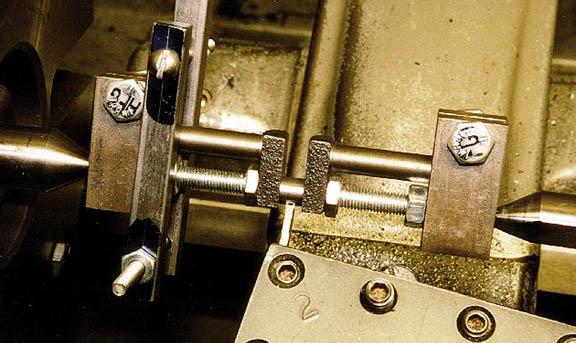
Another thing you MUST do is put a block between the web of the crankshaft. This is to prevent the crankshaft from warping due to the pressure from the centers. This is also known as "springing". I use a small nut and bolt, making an adjustible block.
You have to be careful to not put too much pressure, or your block will spring the crankshaft the other direction. Finger tight is enough. Remember, this block will be rotating on the axis, so there isn't any centrifugal force to make it fly out. The pressure from the centers will also help hold it in.
The nut and bolt are clearly visible in the photo. This photo was taken just after the final cut on the "second side".
Helpful Hint - STP Oil Treatment makes an excellent lubricant if you're using a dead center in the tailstock. Just a dab with a Q-tip is enough.
Helpful Hint, part II - When turning the "second side", put a piece of brass shim between the crankshaft and the lathe
dog, or you might damage the finish.
The fixture used is actually two pieces. What you need to do is build two blocks, with centers at the appropriate offset, which will clamp to the ends of the crankshaft casting.
I used a piece of 3/4" square steel stock, and cut it to a reasonable length. I accurately located two points on each piece, one the center of the main shaft, and the second the center of the crankpin.
 Put the piece in the drill press vise. Center drill for the center. Drill and ream for the main shaft. The hole
for the main shaft should be a smooth sliding fit, but not loose. This photo shows the center for the web in the
block, and the crankshaft inserted in its hole.
Put the piece in the drill press vise. Center drill for the center. Drill and ream for the main shaft. The hole
for the main shaft should be a smooth sliding fit, but not loose. This photo shows the center for the web in the
block, and the crankshaft inserted in its hole.
Turn the block 90 degrees in the drill press vise, and drill a hole through, halfway between the hole for the main shaft and the end of the fixture. What drill you use depends on the size of your block and the size of bolt you use to tighten. I used 1/4-28 bolts, so I drilled through using a #3 drill, the appropriate tap drill for 1/4-28.
Remove the block from the vise, and use a hacksaw to cut a slot between the end and the main shaft hole. This will provide enough clearance to tighten down the block.
Back to the drill press, drill halfway through the block, up to the hacksaw slot, using the clearance drill for your bolt. In my case, this was 1/4". Tap the other half of the hole.
Mount the blocks onto the crankshaft casting. I did this on my surface plate, using blocks to hold the webs
parallel. Tighten down the bolts to secure the blocks to the crankshaft. I used 1" long bolts, which left enough
thread showing to tighten a nut onto the bolt. This is to prevent the bolt from loosening during machining.
The crankshaft in the fixture will look like the photos. Like we did between the webs, use bolts between the webs
and the blocks to prevent springing. Remember, finger tight is all you need.
 I needed to make is cutting tool(s) to turn the crankpin. This tool should have cutting surfaces on BOTH sides
of the tool, so you can machine both sides of the web with the same tool. Between the two cutting surfaces, you have
to cut a notch for relief, or you will get chatter. The diagram should make this much more obvious.
I needed to make is cutting tool(s) to turn the crankpin. This tool should have cutting surfaces on BOTH sides
of the tool, so you can machine both sides of the web with the same tool. Between the two cutting surfaces, you have
to cut a notch for relief, or you will get chatter. The diagram should make this much more obvious.
It is important that both cutting surfaces cut to the same diameter! You have to be careful in setting up the tool to make sure of this. I mounted a piece of drill rod between centers, and used .001 shim stock as a feeler gauge until both edges gave an equal amount of resistance between the drill rod and the cutting tool. It took a few minutes, but it is well worth the effort, or you'll have a crankpin with a taper in it.
Prefereably, the distance between the two points is less than 1/2 the length of the crank pin. This way, the cut of left edge, at it furthest point right, will overlap the right edge, at its furthest point left. (does that make sense?). Basically, make sure that the center point of the crankpin can be machined by either cutting edge.
In this case, I had to make two such tools. The distance between the web is only 1/4 of an inch. I felt that making a larger "rough cut" tool would be better, as I had to break through the scale on the cast crankpin, and it would be an intermittent cut. The "rough cut" tool was about 3/16" wide.
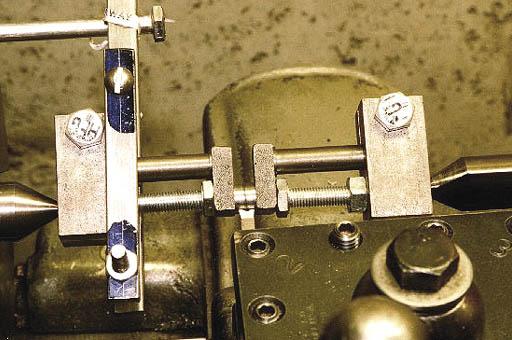 Mount the fixture between centers in the lathe, using the appropriate centers. This photo shows the rough cutting in
progress.
Mount the fixture between centers in the lathe, using the appropriate centers. This photo shows the rough cutting in
progress.
Because of the intermittent cut, I used the lowest backgear speed on my lathe. I also took small cuts, .010 at most. Taking deep cuts could cause flexing of either the crank or the cutting tool, and that's not good.
Due to the small distance between webs, I had to borrow a blade micrometer from my father to measure the diameter of
the crankpin.
 Once I was within .010" of the final dimension, I switched to my "finish" tool. This tool is much thiner than the
rough cut, so I had to take very light cuts or the tool would have flexed. Very carefully I worked down to finish
dimension. If you're a little off, don't worry about it as you can always make the connecting rod bearing to fit!
Once I was within .010" of the final dimension, I switched to my "finish" tool. This tool is much thiner than the
rough cut, so I had to take very light cuts or the tool would have flexed. Very carefully I worked down to finish
dimension. If you're a little off, don't worry about it as you can always make the connecting rod bearing to fit!
The webs have to be machined to dimension. Its really a non-critical dimension, so I could have gotten away with not doing it, or just using a file. But, I like a fully finished crankshaft...
While the fixture was still in the lathe, I turned a nice radius on the ends of the webs. The plans called for this to be flat, and square to the sides, but I like a radius there, so I put it there. I had to check that the ends were fully machined (no rough patches) and the length of the webs was right. (sorry, no picture...)
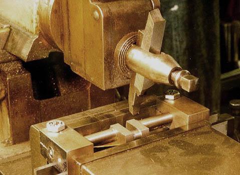 With the crankshaft still in the fixture, I used my shaper to machine the sides of the webs. The photo shows the
setup. I put shimming between the parallels and the webs to prevent any downward flexing.
With the crankshaft still in the fixture, I used my shaper to machine the sides of the webs. The photo shows the
setup. I put shimming between the parallels and the webs to prevent any downward flexing.
At this point, you can take the crank out of the fixture and admire your work! BTW - Put the fixture in a location where you'll be able to find it the next time you make a crankshaft with these dimensions.
 It might be considered overkill, but I lapped both sides of the main shaft to finish size. Lapping ensures that there are no high spots on the shaft, that both sides are the same dimension, and also gives a nice smooth finish. It certainly isn't a required step , but I did it anyway.
In my case, I used a piece of scrap round brass as the lap, about 1/2" long. Brass is softer than cast iron, so the grit from the lapping compound would become embedded in the brass, instead of the cast iron. I drilled an appropriately sized hole in the middle, and the used a hacksaw to cut a slot from one side to the center hole.
I also made a holder out of scrap aluminum, a hole in the middle large enough to hold the lap, a small shoulder on the "back" to keep the lap from sliding out of the holder, and a tapped hole for a set screw from the side to the center. The set screw is to tighten the lap as you're working, so use a size large enough to exert some force on the lap without stripping the tread.
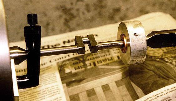
Put the lap on the end of the crankshaft, and mount it between centers in the lathe. Take the tool holder off the coumpound so it is out of the way, and cover the ways. Firmly grasp the lap, and turn on the lathe. Move the lap back and forth across the peice, don't hold the lap in any one place for too long.
I was taught that the lathe speed should be set such that as you move the lap back and forth across the piece, you form a 60 degree "cross hatch" pattern with the compound on the piece. For me, I uses the highest backgear speed.
As you work, you'll feel where the high spots are. When the lap moves with little resistance, turn off the machine and tighten the lap. Don't tighten it so much that you can't hold it as the crankshaft turns in the lathe. I was amazed at how quickly the first few "cuts" went, but that shows how the turned surface as a lot of very small high spots due to the relief in the cutting tool.
I also found that my hacksaw cut across one side wasn't long enough, the last few times I had to tighten it took some effort. Next time, I'll cut at least 3/4" thru the brass lap. I would NOT recommend cutting all the way thru, however.
I didn't lap the crank throw. Its only 1/4" long, and making a lap that I could move back and forth that short of a distance seemed dangerous. I didn't think I could hold it and move it so it stayed perpendicular to the throw, so I figured that lapping could do more damage than it was worth.
Helpful Hint - When lapping, you should protect the lathe bed from any dripping compound, or else you might slowly lap your lathe bed as you move the carriage over it. I used several sheets of newspaper, which can be seen in the photo. Other people I know have used tin foil. If you do get lapping compound between the carriage and the bed, remove your carriage from the lathe, and clean both the carriage and the bed thoroughly!
To learn more about lapping, check out Chris Heapy's Workshop techniques page, a great reference for lathe techniques.
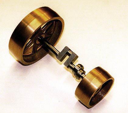 Here's a picture of the finished crank, with the flywheel, beltwheel, and valve eccentric mounted. Looks pretty good, don't it?
This technique can be used for multi-cylinder engines as well. Just make the end blocks sufficient size for all the centers.
You can use this technique even if you don't have a cast crankshaft. If you're building a crankshaft up from one solid piece, you don't have to worry about bolting the blocks on, make the crankshaft a little longer, and mark then ends with both centers. If you're building it up from multiple pieces, once everything is together, bolt the blocks on.
I know I already said this, but they bear repeating for people who didn't read the full text:
![]() This page is always under construction!
This page is always under construction!
Last Updated March 27, 2003
All photographs and text © Mike Boucher. Ask permission if you want to use any of it!
For more info, contact me
Return to Techniques page